eLLF (Long-Low-Flexy) | Loaded Dervish or Tan Tien | Caliber 10 Inch | Dual Drive | Mounting method | 10s1p | Dual FOCbox

I currently cruise around on a loaded Dervish or Tan Tien with Paris trucks (dropped through) and Otang InHeats and Balut’s respectively. I know the Balut’s were recalled a long time ago, but i just couldn’t bring myself to give them back. I love the flex of these boards and how low they are to the floor and absolutely want to keep these features as a priority.

This will be my first electric board that i am hoping can augment the final leg of my usual commute off the train and on to work or uni. I am on my way in to my third year of Architecture school at the University of Sydney which is a 12 minute walk (1.1km) away from the nearest station. Obviously that isn’t too far at all, i’d also like to get maximum low profile rage to allow longer cruising for recreation.

I have a Shapeoko 3 CNC router and access to a 3D printer, I am hoping to use this project to learn Fusion 360.

I’m just over 6 foot and 100kg’s and there are some fairly steep hills around in Sydney, so i’m going for a dual drive first board. With the desire to keep the drop thru trucks, I am thinking it perhaps best to mount the motors outside the board as opposed the inside/under the board as appears common in the threads i hav trawled through. Any reason mounting outside is not common?

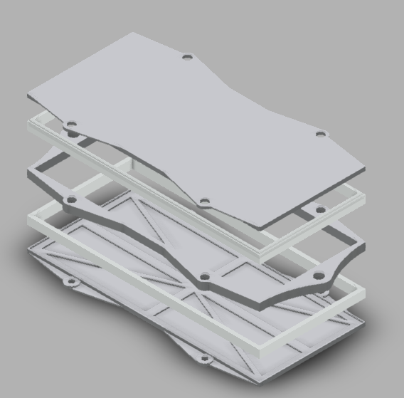
I was thinking of using long but thin thin LiPo batteries with their long side mounted perpendicular to the board. I was thinking of CNCing a fairly tight enclosure for each battery, the battery would be suspended conceptually similar to the way it is done with condenser mics. Each individual battery enclosure would be mounted using a nutsert/bolt/screw at each length wise end of the enclosure’s, they will also be elevated and suspended/offset from the deck with a silicone ring or bush etc. I would also like to suspend metal bash plates over each battery compartment using similar silicone spacers from the front facing wall and bending over the top face. The idea being:

  • Each battery is suspended within it’s own enclosure and dampened for vibration.

  • Each enclosure is somewhat dampened for vibration by small contact mounting points of silicone type material.

  • Aligned horizontal fixed mounting perpendicular to length of board allow length wise flex of board to remain.

  • Nutserts in conjunction with silicone bush type mounting for battery enclosures will facilitate torsional twisting of board.

  • Metal bash plate suspended/cantilevered above battery compartment provides a strong, puncture proof layer of protection for batteries

  • Three layers of separation creates a 'crush’ability - where the combination of bash plate + Air Gap + Enclosure + Airgap may absorb the shock of bottoming out due to low clearance on road surfaces.

Luckily @namasaki has a proven battery and BMS template that get’s me most of the way there. I will be using 5 x ZIPPY Flightmax 8000mAh 2S1P, as they are slightly thinner whilst also proving 60% increase in capacity?

http://www.electric-skateboard.builders/t/the-namasaki-rebuild-10s-lipo-w-bms-dual-carvon-v2-0-focboxs/31596

I have ordered a couple FOCboxes and a nano-X remote controller. I will now start on CADing and prototyping some enclosures for batteries, BMS and FOCbox’s and working out elegent wiring, braiding, grommets and stuff like that.

If anyone has any advice on mounting motors in such a tight space, that would be really appreciated. As previously mentioned, i’m thinking mounting the motors outside the wheels as in my head that may provide the best clearance for my drop thru & board requirements. (I am fairly attached to the drop thru) Maybe one motor under and one outside? Maybe it won’t be an issue at all? easy fit? As far as i’ve worked out i’ll need two 190kv motors. Since i have a hobby CNC i suppose it makes sense to have a crack at making my own mounting brackets, i could 3d print the wheel pulley custom for my Balut’s and purchase a belt and motor pulley.

The other cheap and actually really clean possibility is to pickup dual 72mm hub motors and trucks I saw either on eBay or Aliexpress? They seem to have really low kv (75ish?) rated motors for 2s-6s. No clearance issues, no linkages to fail, no major maintenance and probably cheaper overall. I have seen the larger hub motors (90mm), but being as low to the ground as possible is important to me. I am a pretty heavy guy, plus my gear and fairly steep hills, i’m looking for max torque and range, speed is a very distant third requirement.

1 Like

I have designed my battery enclosures in fusion. I will iterate through a few more designs on my way to FOCbox and BMS enclosures. Yet to design the polyurethane stand offs which will suspend these enclosures slightly off the board in an attempt to isolate each component from each other, vibration and board flex.

Would be nice to do CNC routing on both sides, but can’t be bothered at this early stage. Should be done with CAM tomorrow and get going on the CNC router the day after.

The enclosures are 187x85x25 ish from memory. The middle and top/bottom layers will be milled out of aluminium and sandwiched by HDPE.

5 Likes

IMG_0867

University has drained me of my time for the last many months, as well as waiting for bits and pieces to arrive. Here is an update of where my motor mount currently is at. I would like to decrease the upward angle, but it is currently perpendicular to the flat top part of the axle, which seemed to make the most logical clamping sense at the time.

IMG_0055

i think for my next build, i will mount my motors in a similar manner, but at an angle much closer to horizontal. I had originally imagined the increased angle was absolutely necessary to avoid clearance issues, especially since the mounting is outside the wheelbase, But like a lowered/stanced car, it will just look so damn good with the motors more or less sticking straight out. My next build will be using a Tan Tien which is slightly shorter board. Given I am about 6 foot, i’d like to be able to stand on the tail kicks for manoeuvrability.

I will pragmatically post here, though i wax lyrical about this build, design, tech and culture on my website if you have time to kill, check it out. Make 0001: Mixed Modal Transit

4 Likes

Interesting motor layout. You really wouldn’t have enough clearance with a dual diagonal layout, even a reverse mounted dual diagonal?

There is 1 or 2 cm clearance to ground in total, were I to mount the motors under the board. This does not seem like all that much to me. Particularly on my Tan Tien, with Otang Baluts, a 72mm wheel where the flexibility of the deck will move the motor vertically in an arc a fair bit due to the flex.

IMG_8440 [Balut’s were recalled a few years ago, but I keep them around, because i’m a rebel and they look so damn good.]

Mounting motors outside the wheel base enables you to use a regular width truck, whilst enabling dual motors of infinite size/length also can give you that wide fast car look, if mounted on less of an angle than my first prototype. I am using standoffs to space out the motor, so it will be interested to see how it holds up in use.

IMG_7389

On a more design/metaphorical standpoint, why is it that builds tend to tuck and hide their motors away from sight? and instead put the whole board on riser pads. I think that looks shockingly bad, last I checked the Rolls Royce phantom sits low and long on the road, the Mclaren P1 is low and very wide. I am yet to see to a Ferrari with a lift kit though.

1 Like

Home stretch of my first build, which has taken a whole lot longer than I had originally anticipated, my desk a crime scene! I’ve done a couple things a bit different to what i’ve seen whilst doing a bit of research for this project, so here are some photos and a bit of commentary as my small contribution to our collective learning.

Studies and sluggish shipping times to Australia have slowed me down a whole heap. For the aussies, i picked up BMS and charger via aliexpress/china, motors and a couple cables from DIYe state side, nuts/bolts/ports/connectors at Jaycar who have a tonne of great stuff, but are a slight rip off sometimes. They wanted $25 for a couple small spanners 4mm-8mm, Supercheap Auto had the same set in a chamellion finish for $2. Bunnings for common fasteners, seals and a good sanga [“sanga”/“Sausage Sizzle” - a sausage in bread with onions and sauce, sold at Bunnings everyday by community groups/sports teams etc.]
[“Bunnings” - Hardware store like Masters, but better since Masters folded down under]

Enertion up (relative to me in SYD) on the GC have undeniably focused and concise design, in the Apple - “Courage” vein, which I ascribe too. There is a procedural nature to their products that is absolutely head and shoulders more complex and precise than what most others vendors in the community are doing. They got my business for FOCBOX’s and nano X via that debacle of a halloween sale - when halloween isn’t even really a thing down here. Were their R-Spec motors still available I would have opted for those as well. Sidebar - why not an Australia Day Sale? or PM Killing Season Day Sale? those both come around once a year.

[Rant start] Sidebar 2 - Enertion has a price of X on the site, you add it to the cart and have a look in the cart; The price jumps up because GST [VAT/TAX] is not included in the original displayed price! Shoulder shrugs from the internationals, but here in the AU, we don’t advertise anything like that ANYWHERE, this is misleading to consumers and not in compliance with ACCC guidelines on Displaying prices.

When you present prices to your customers, you must state the total price of the good or service as a single figure, which is the minimum total cost that is able to be calculated. This should include any tax, duty, fee, levy or other additional charges (e.g. GST or airport tax).

Statements such as ‘Was $150/Now $100’ or ‘$150 Now $100’ are likely to be misleading if products have not been sold at the specified ‘before’ or ‘strike through’ prices in a reasonable period immediately before the sale commences.

If a business has a policy or practice of discounting goods when not on sale and uses two-price advertising in relation to sale periods, there is a significant risk that the use of two-price advertising will involve conduct that is misleading. The business would be representing to consumers that they will make a particular saving if they purchase the item during the sale period, when this is not necessarily the case.

  1. Advertised Enertion prices do not include tax, this is a breach of ACCC guidelines.
  2. The Unity sales that currently display a strike through of $555, when this product was never available at that price. This can therefore not be considered a “reasonable period”, thus in breach of ACCC guidelines.
  3. I argue the practice of changing Unity pricing in conjunction with additional 11/12% discounts via email creates multiple price points which again, in my view is not compliant with ACC regulations.

It’s not like this is some obscure international company. You are right here in Australia, do the right thing and comply. @onloop Love your hardware! You don’t cheat the design process and it shows in the hardware. But business practices require a slight rejig. [Rant end]

Conceptually my separated enclosure idea remains, though the individual case designs have been simplified. For each module, i have 2 x threaded insert nuts from the top of the board, with a bolts coming through the the module from the bottom. The two hole locations are centered across the modules along the width of the board. Between the board and module I have placed a neoprene roofing seal with a couple washers, this floats each module 2ish mm of the surface of the deck underside. This is an effort to maintain the flexibility of the loaded deck I am working with. Flexibility and speed don’t usually mix - i’ve never seen an F1 team actively seeking to add flexibility to the chassis, unless we are talking about front wings but I digress. I don’t like that the bolts are exposed that way, ideally i would have had the flats of the bolt head facing the floor and the nut facing the board, but it would have then required spacing the modules further away from the deck, or a more complex outer module design. This was the pragmatic approach.

I’m using the Bestech 10s BMS, which is a nice piece, with zippy 8000 flight max 2s1p lipo’s. on my test ride down the hallway they are working as expected, however I am pretty disappointed in the variance of the physical size. LxWxH they have anywhere from 2-5mm variance, which sucks when your design intent calls for uniform sizing, though that is a lesson learned. I will perhaps use a hard case LiPo next time. I’ve got a foam seal top and bottom of battery to ‘float’ them within the module. In conjunction with the neoprene seal of the module itself, this is aimed at isolating the batteries from harsh vibrations.

I have attached the FOCBOX’s directly to the aluminium of my enclosure with a a thermal pad in between, this should help to disapate heat. A similar strately was employed with the heat sink on top of the Bestech BMS, though in that case it is spaced from underneath in order to push the heat sink in to contact with the aluminium plate of the module mediated again by a thermal pad.

I have used nylock nuts in most places and am now going through the every nut and bolt to add loctite and tighten it all down. I am still yet to see motors mounted in the way that I have done it. My main goals have been to maintain my boards flexibility and a stern unwillingness to raise my board via risers or bigger wheels at all. Via this configuration I can give the motors ample clearance to ground without the need to add risers. Outside mount avoids clearance issues between motors and to deck kicktail.

For the car guys, my mount cap is heavily inspired/ a direct copy of the unbreakable 4 bolt main bearing caps on big V8’s, in combination with the thickness of my mount plate, I have found them to be absolutely rock solid.

To combat potential concerns for rigidity, I have used 10mm thick aluminium stock for the mount plate, with the side effect of acting as a quasi heat sink. The 4 stand off posts are aided by a small pillow block bearing which is attached to the motor shaft and then bolted the the main mount plate. In this way I try to account for any decrease in mount rigidity and at a stretch argue my mounting method is more secure/rigid than standard mounting methods, whilst also applying less pressure to the motor shaft for inferred better reliability.

2 Likes

Which part is the “mount cap” you compare to main bearing caps on engine blocks?

I like your motor configuration, I would love to see how it holds up with usage. My concern would be the torque being exerted on the motor stand off posts, I assume they are steel? or any other hard metal I guess, regardless, they are resting on relatively soft aluminium. They might get loose if the toruqe makes the posts “dig” holes around them selves in the aluminium. Of course this is easily fixable by just having washers on the aluminium plate to distribute the stress better.

I also dont see how you mount plate is acting as a heat sink. There is no thermal contact between it and the motor. Which might be the only immediate drawback, that your stator has no way of spreading the heat effectively to any other part.

I have a box of washers sitting next to me wondering why they were not used. Having used a fair wack of loctite and slightly stripping a few of the nuts and bolts, I might just test it out today and see how the whole thing holds up.

IMG_2817 The bottom of my mount is what I was comparing to a 4 bolt main cap off an decent V8.

IMG_4761 Top down view of the motor mount.

IMG_3520 I am fairly happy with the clearance beneath the board. I’ve lost perhaps 30mm of clearance under the dek at stock drop thru height. You can see the Hall sensors up in the air there, still waiting on some JST plugs so i can connect these up to the focboxes. Why i purchased white shrink wrap is completely beyond me, that sh*t is ugly AF!

IMG_9496 The shape of the board means the end modules protrude from under the deck slightly, which became the spot I placed my charging port and on/off switch. Perhaps i should find some sort of cap to keep it free of debris. the sides of the modules are cut out of ikea chopping boards. You see the focbox, bluetooth and nano x receiver LED indicator lights blinking through which is a nice piece of user feedback when powering the board on.

IMG_3427 My enclosures have taken up pretty much the whole length and width of the board, which makes it kind of awkward to handle from the side with the bolts sticking out and nowhere to mount some kind of side carry handle. I will have to cut those bolts down and have been considering an overlapping outer layer of some kind. I am also tall enough that i can’t drag the board next to me holding the motor truck without the other kicktail hitting the ground.

IMG_7101 You can see the gap between each module and the deck in this picture. My enclosures are definitely not water resistant at all. They are bolted down pretty tight and I could have sealed them all up nicely. I could have sleeved the cables and run them through grommets or at least caulked up the holes, but i didn’t in a rush to get it done.

IMG_2662 Topside view of the insert holes. There is one bolt which sticks out of the board because i accidentally picked up the wrong length bolt and didn’t realise until i had already bolted down that module. It was such as massive pain to bolt these modules together that i don’t even want to think about taking it apart to change it. I was forcing a pliers between the nut and enclosure on to the bolt to stop it from spinning, whilst i used a spanner on the bolt to tighten it down enough to expose the bolt past the nut. Then i was holding the top of the bolt with pliers which using the other hand to use a spanner on the nut. 10 x per module, x 7 modules.

I updated firmware and did initial setup using the latest VESC TOOL, which is a nice piece of software, still not the best UI, but it stepped me through each stage nicely. The esk8matics/telematics/Xmatic iOS app appears to be working nicely as well. I am wondering if squeezing my focboxes, nano X receiver and bluetooth receiver in to a aluminium sandwich will cause connectivity problems, so will gingerly traverse my suburb tomorrow to make sure that isn’t an issue.

Next step is to search out a VESC setting guide as i’d like to make sure i’m getting maximum though safe performance. tips, tricks and rules of thumb etc. would be appreciated here. I went with FOC and vaguely default values.

4 Likes

Your motor is backwards.

i mounted it this way on purpose

2 Likes

Why?

10 char

full answer is fleshed out across my first few posts, but the short answer is clearance

1 Like

Turns out 4 x m4 bolts and nyloc nuts are not enough too stop motor mounts from coming loose. Also had my motor pulley’s come loose, despite loctite.

Managed to stumble upon a long dead thread where a ‘gear blank’ was used to make some nice custom pulleys. Basically the gear blank is a massively long pulley and you can machine the back of the pulley to fit any wheel you want. I had imagined all the pulleys we get in kits were milled out of blocks of metal, but i suppose it makes much more sense for it to start life as these long geared extrusions.

In my quest for ever more low-ness, I am looking to pickup some of this gear blank and create some custom pulley’s for orangatang Balut wheels (72.5mm) as a unique personal project. These are now extremely rare, so it will be nice to be just a little more unique. Hoping to either have the pulley with a inset bearing and prongs going through the spokes, or use a front plate and bolts for ultimate security.

More long term, i’d like to make a nice pulley for some Biggie Hawgs. These wheels are only 70mm in Diameter, but have a seriously massive 69mm contact patch. That fat drag car look. image They are a centre set wheel, so may end up with fairly long/wide pulley which may necessitate using long shaft hangars like torqueboards 218 and bearings within the pulley itself.

I’ve found a local supplier of the gear stock (Mini Bearings AUS), they have any number of teeth listed from 12 right up to 72. I will be using this thread build as a base to work from. If someone can give me a bit of guidance in relation to gearing, that would be super helpful.

I am thinking having such a wide wheel and literally unlimited motor size, maybe I can try to get motors suited to high speed, and gain the torque back by my gearing? Maybe that isn’t even possible? Basically i’m wondering is it is possible through correct motor selection and gearing to have high torque and high top speed?

4 Likes

Potentially bricked my board this afternoon. :unamused:

Hopefully it is just flat, will charge it when I get home and see how we go.

image Basically went up and over a steep hill, tried to punch it over the top and didn’t really get the usual top speed for around 200m. 200ish metres after that it was cutting out. Stopped and pulled my phone out to this and a supposedly flat battery.

Will throw it on the charger and see how we go later tonight

False alarm, it’s just flat.

I was relying on Xmatic app saying I had 50ish percent battery, perhaps that hill was just a battery zapper.

1 Like

How is your build coming along? I really love the feel of Loaded boards, so I’m very curious how they feel powered!

:thinking: boosted has been using them for years now.

I had no idea. Haven’t tried a Boosted, anyway.

It has been running great! I’ve been up some very steep hills and have hit an indicated 50km/h. A little voltage sag, but fairly minimal. My build is super heavy and long, which is not great on the train and on a bag.

I just picked up loaded tessaract for a steal, got to love their boards, but not a full price. Pricing in the skate industry is ridiculous. I’ve got a tan tien as well, boards with kick tails are nice for manuverability. The dervish and boosted boards do not have kick tails which can be slightly annoying.

The super wide torque boards trucks make turning extremely difficult, I understand now why evolve went with the double kingpin. I put Paris 180 trucks on the front to try and add a bit more turning and dive to the front, but that TB wide truck really sucks for turning.

The Paris truck and my Orangatang in heats are lower in height than my powered TB + ABEC 11, giving some nice front rake to the board. Aiding in power delivery/stability, helping to keep me on the board when pinning the throttle.