I completed my first build “BIG TORQUE” over a year ago and feel like many lessons have been learnt during that process. I was planning some upgrades but small things i wanted to change resulted in needing to change a lot of hardware.
A friend with a boosted board also decided that he wanted to go the DIY route so we decided it might be worth it to just start again from scratch and build a pair of boards together.
Following on from BIG TORQUE the goal here is a powerful board for a big rider however this time i want more range, more reliability and more comfort. lots of failures last year due to water ingress and mechanical breakages limited my riding time so this build im going to spare no expense in making things robust and reliable.
I plan to use this page as a detailed log and post regular updates on the build however i have a bit of a backlog so expect quite a few posts at once.
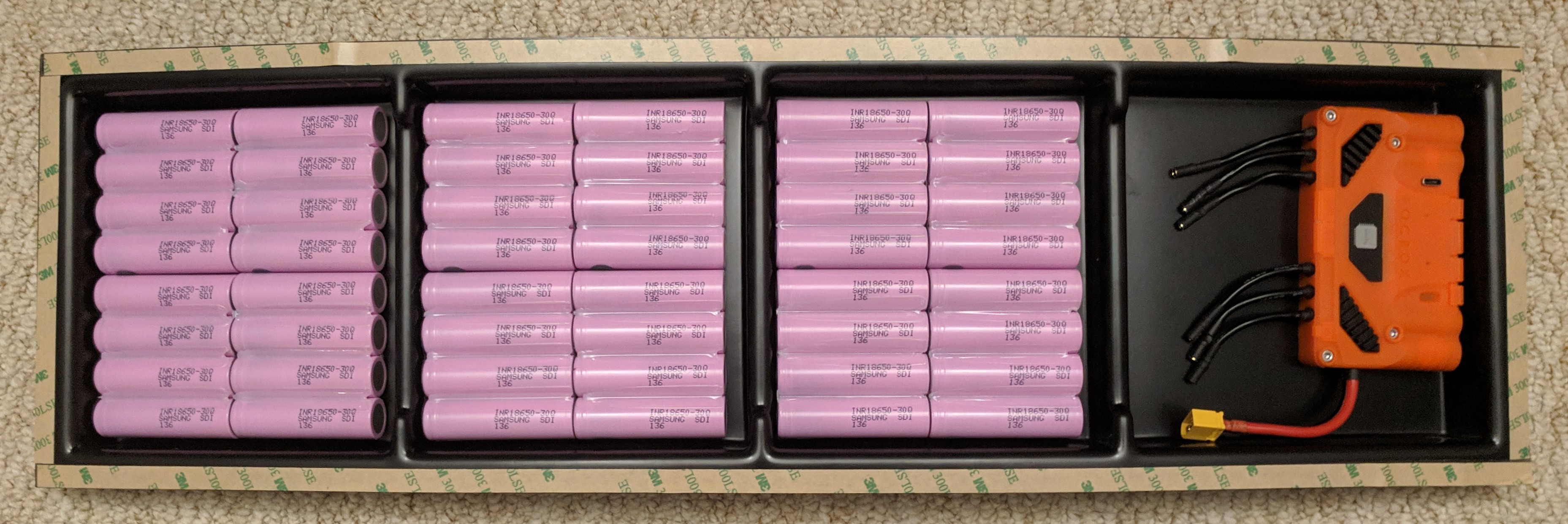
After spending a long time last year re purposing batteries we decided now was the time to start building our own packs so we split the cost of a tab welder and committed. We chose 30q because they seem to offer good range but also long life. 12s4p should be 12Ah or about 520Wh which is double the capacity of my old pack. for both boards that 100 cells
DIY enclosures are hard . . . very hard. After building a few now i have mad respect for those on the forum that make awesome enclosures. I have learnt that if you want something reliable then just buy one of theirs cause it will save you a shit ton of time and cost down the line. We went with the @Kaly enclosures cause it looks great and was very well priced.
As a large guy i found that belts needed to be fairley tight to avoid skipping witch means that they didn’t last that long. After having a few snap whilst breaking I have been eyeing up some gear drives. Decided to go with @3DServisas Gear drives with the 5:1 reduction. The finish on these is great.
My old Trampa board is built like a tank but the street carve deck doesent fit the enclosure well and the mini spring trucks wont fit most gear drives so i decided to move to a full size ATB. I also decided to switch up from skate wheels to urban treads and also get bindings as i have eaten asphalt more than once due to cracks and bumps on local country roads. I went for the 6.5" urban treads to keep the top speed below 35mph and also to allow running at very high PSI when i need the range.
One of my old motors got knocked at some point and now resonates as certain frequencies. the Maytech motors having heavier than most however should be far more robust due to having sported motor bell at both ends. Might have to cut those long shafts down tho
Last time I had a faulty battery i couldn’t work out why by board kept cutting out. i had no way of checking on the battery and no way of fault finding. This time a Bluetooth smart BMS will allow me to view the status of all cells in the battery. I also got a good case of face-pavement once because i hit the power and my BMS over-current decided to cut the power, after that i will only run BMS in bypass for discharge. This means i can get away with a smaller (20A) charge only BMS.
Since im bypassing the BMS for discharge i need a way to switch the board on and off. Decided to use the Unity as it has claimed higher output power than the old FOCBOX and also has integrated anti-spark power switch.
First job was to assemble the Samsung 30q cells into 4p groups. I glued the cells together with hot glue. To ensure good alignment the cells were placed in some makeshift cell holders.
Excess glue was “squeegeed” out with the corner of a credit card to ensure a clean join with plenty of surface area.
Cell positives were then fish papered to avoid any shorts.
I am using @KalyCELL Fuse pcb kit to join cells in parallel and make it easier to join them into a pack. Additionally this kit means that every cell is individually fused adding another layer of protection in case of failure.
Nickel strips were soldered onto the pcb’s using a jig that held the strips in place, this means very uniform strip positions. large tabs are for battery negatives and thinner “fuse” strips are for positives.
PCB and cells then fit into an alignment JIG ready for tab welding.
At this point you could easily weld the cells by hand . . . but when there is this many cells to weld why do it manually?
Cell groups have had large clear heat shrink tube applied over them to give another layer of insulation and protect them whilst being handled and moved around. clear heat shrink was then carefully cut off of the terminals in preparation for soldering once the pack has been glued.
The packs are very solid at the point, not really concerned about damage from vibration or flex.
We cut some wooden spacers to go between the cells to ensure that there was no rubbing between parallel groups and that everything fit snugly.
After some recommendations from work colleges we decided to use PURAFLEX 40, a “high modulus polyurethane sealant and adhesive” to glue the packs into place. We started by making sure the dividers were in securely.
Next we placed glue under the cell packs to ensure they stay in place.
The X shape is so that as you press the pack down all the air is pushed out and you don’t get left with bubbles underneath.
A final bead was then laid around the edge to make sure that cells stayed secure and help to stop any ingress that might occur.
2 glued up batteries ready for soldering.
I had my doubts about the PURAFLEX but it has actually worked our very well. After 48h to fully dry these packs are solid. I can hold one of these upside-down above my head and shake it vigorously without worrying that any damage will be done.
It also lasted much longer than we thought it would, we brought 3 tubes thinking we would need lots but we finished both boards and only used about half a tube.
Next job was to sort out the enclosure mounting hardware. The Kaly enclosures came with threaded inserts which needed to be drilled and tapped into the deck. Unfortunately i needed the pillar drill for this so had to do it at work (meaning no work in progress pictures).
In order to correctly position the Inserts we first clamped the enclosure to the deck in the correct position, making sure that no bolt holes overlapped the binding bolt positions. Due to variation in the binding positions on the 2 decks this means that enclosure position is slightly different on each board. Also worth double checking where the front of the enclosure is because they are not the same at both ends, make sure the binding bolts are in he correct positions before starting drilling.
We drilled through the enclosure mounting holes and into the deck with a pilot hole then removed the enclosure and drilled to the full width for the insert. The depth stop in the pillar drill was used to avoid drilling through the top surface of the deck.
Inserts were then wound in slowly with a hand drill whilst applying lots of downward pressure. This can be slow and frustrating but ensures that you don’t damage or strip any threads.
Finally both board have all mounting hardware fitted (and we were very itchy from all the fibres).
We decided to usecopper braided cable to join the parallel groups together. The braid is 10mm wide and 1mm thick allowing it to have a lot of flex. It has 6mm2 cross section of copper and is rated to 63A. we decided to use 2 pieces of this smaller braid instead of 1 larger braid as after doing some tests we found that the thinner braid was easier to solder and remained more flexible for the same current rating.
The trick to getting the braid to remain flexible over short lengths is that you need to heat it quickly enough that you get a good joint but without allowing the heat to spread causing the braid to “wick” up the solder. This required us to source i larger soldering iron than i would usually use. luckily someone lent us an 80W iron without temperature control which would easily reach the required temperatures.
We also added an XT60 on the output ready for the Unity to connect to.
Damn… clean building going on. That 5p spot welder is dope. You should sell 5p packs so people can assemble their own battery from there. You could really pump them out with that setup.
@Skunk thanks. I had considered selling them but i don’t know if i want to be liable for other peoples safety. If my board cuts out or catches fire it will suck but whatever, if someone else had a problem because of one of my batteries then that would be hard to live with.
Also even if its automated its still surprising time consuming. I don’t now how much money you could actually make from reselling cells that are joined together but i dont think it would be worth the effort. I think that most who are already buying pre-welded cells would also want them to be built into a pack and bms protected so there is no risk to them.
IMO a better idea would be to sell an enclosure with an integrated and protected pack that you can just add your own electronics to. This could make diy builds super easy and low risk for the amateur DIY builder.
Balance cables and an XT30 have been added to the Battery. The balance cables are routed to the LLT smart BMS and the XT30 is to allow separate charging of the cells. This charge path will probably have an inline fuse added at some point.
Kapton tape is used to insulate all bare conductors on the battery and also keep balance cables from moving around.
As we have been building a board each they are slightly different but we are trying to keep the layouts as similar as possible.
Were still waiting on a Unity but everything seems to fit well.
BMS is up and running but initially seemed to be having troubles getting correct cell reading for the first 3 cells. eventually we found that this was because you must have the B- port connected in order to get correct reading for the first few cells. Now it looks good, all cells seem to be at a healthy storage charge
Do you even need cell level fusing if all your parallel groups are so well insulated from each other? (I know that’s just what the Kaly kit comes with, but asking in general)
@Jaydawg56 I would love a DieBMS and all the vesc metar integration it comes with. unfortunately it’s also huge and designed to switch lots of current which I don’t need with unity. If there was a smaller charge only version it would be an easy choice but for this build it’s not worth the cost and inconvenience.
Not sure on the width but I can check next time I have the calipers out.
@rusins most common battery fault is that the positive nickel strip breaks through the heat shrink and contacts the negative cell casing. With these strips they will just burn at before any damage is done to surrounding cells (causing a chain reaction). Whilst I don’t think it’s very likely to happen on a pack this well insulated, it costs almost nothing to have the added protection.
As we needed a way to secure the Unity and BMS in place we decided to make a thin aluminium panel which they would both screw into.
We used aluminium as it should help sync some of the heat from the Unity during riding and the BMS during charging. Hopefully the large surface area will help some of the heat escape through the bottom of the enclosure easier.
Its not that fancy but it does the job. If i had access to a CNC that could cut aluminium i might have made something fancy but some times a hand made thing will do just fine.
This was the first time powering the unity off the battery but everything seems to be working so far
Next task was building the geardrives. First job is to mount the plate gears to the wheels. then mount the motor mount plates to the trucks. We can then check that the plates are parallel to the motor gears and lock tight them on.
Motors are then mounted and adjusted to ensure correct gear meshing.
Drive gear is unbolted from the wheel and placed into the drive. We filled them up with loads of grease, not sure how much you need but fuck it.
Outer case and steel plate are bolted on and the o-ring seal is fitted to keep all the grease in.
Wheels fitted back onto both sides (and also front truck)