Having binged on the knowledge from this forum for my 1st build, and during the last few months. Guilt has motivated me to give back a little, and do a build log for build#2
Build#1 was a learning curve, to get some of the basics of boarding out the way. Its equivalent to a meepo V2, considering it has most of its parts from Meepo !! But I now want something faster and will trouble me less with potholes, gravel, grass, small puppies etc.
< Waterproof to IP66. Every OEM board should have this rating. No excuse.
< Undermount battery+ESC. No pelican cases for me !
< Chaindrive system instead of belts.
< Built-in head+taillights. Wired to battery
< Sub £1000 direct board costs. Not a hard target, but a nice aim with a splash of optimism.
Having spent months going through pros/cons of various parts and their relevance/cost for me, I’ve compiled a spreadsheet full of data. I’ll upload a final, polished copy once the build is finished.
First build purchase being a complete MTB from ebay £75 shipped. As costs go this feels like a good start, considering RRP trampa deck and trucks alone would set me back £350. Plus I have a functional MTB before I’ve even started.
Deck is lightly scratched underneath, but in great condition, and will get covered by a giant battery anyway. Trucks are also scratched but perfectly functional and don’t pose an issue for me, especially for the price.
As seen above, board came with 9" tyres on MBS tri-spoke hubs. As nice as they are, they’re a little large for me. Also extra mounting points on the hub for the driveline would be useful. I’m looking to replace them with Trampa 7" Hypa wheels. at £30X4=£120, wheels become more expensive than the rest of the board …
< Custom flex battery using Sony VTC6 cells. Aiming for 12S5P.
<BMS not fully decided but will likely be a cheap charge-only solution.
<Enclosure may be custom, based on Eboosted version above, or I may splash out and save myself the trouble.
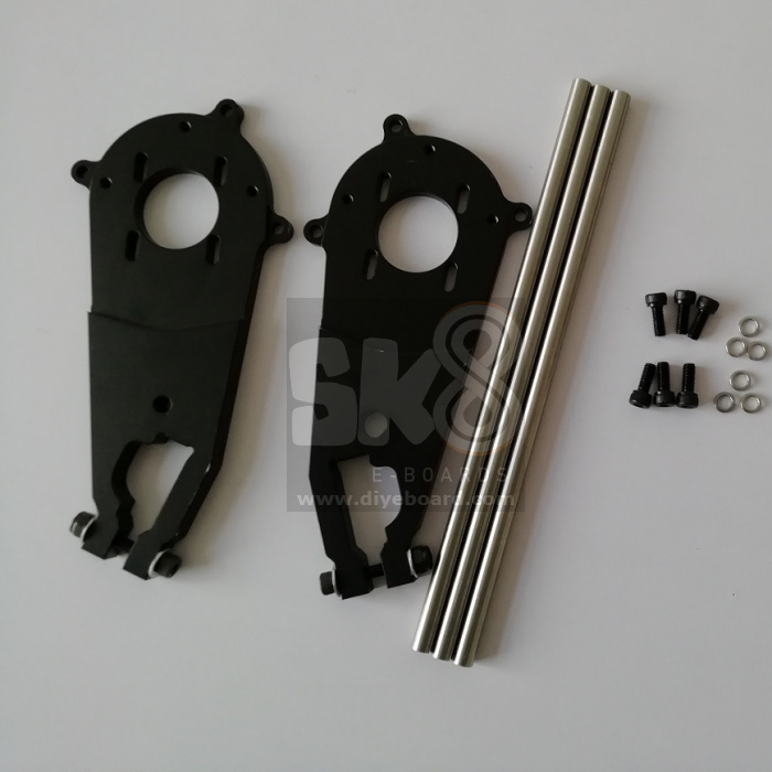
<DIYEBoard ATB motor mounts. They were designed to fit their own cheap ATB trucks, but fortunately the trucks appear to be near identical to the old MBS trucks (copied designs wouldn’t surprise me). So hopefully I can get away with using these. Praying these are robust enough too !!
Current thoughts on hardwired lights is to wire a buck converter straight to battery, set output to power range of the lights and connect. I may splice a mosfet between lights and buck to act as a switch using the 5V UART output from the VESC, depending if I can get a remote to operate that switched output. I know this is possible with the cheap Chinese ESC’s as I have used this in build#1. Any advice on this would be greatly appreciated !!
Plenty of other parts are in the works and will be added in due course
Trampa 6.5’’ urban treads with hypa hubs came today. Eagerly fitted them and…
They’re 5mm thinner at the bearing the my old MBS tri-spoke hubs. So the wheel nuts wont hold the wheel tight due to the protruding section of unthreaded axle.
Fortunately I ordered spare bearing spacers, so I chopped a pair into 4 x 5mm sections and spaced the wheels out to meet the nut… Its always the small details that bite you !!
I should also point out that while these are gorgeous wheels, for the £120 price tag, Trampa could’ve at the very least included VALVE COVERS of all things !!
Quick scale mockup of the chaindrive system. Using T8F chain on a cardboard replica of the 115mm sprocket which should be arriving shortly. Quickly printed off some spacers to see what length is required. I think I got it pretty accurate with M4x20mm, so I’ll be ordering some steel ones. I’ll be using male-female pillars so they can be threaded into the original hypa M4x35mm bolts, then fit the sprocket onto the male ends and fix down with the original hypa nyloc nut.
Nice build man, I actually just swapped out my 6.t’ urban carver wheels for Mbs 8’ as I plan on going undermount with same enclosure from eboosted but I believe it will be a tight fit for ground clearance.
Cheers dude. Yes I’m keeping an eye on ground clearance particularly with the flex involved. Might have to move up towards inline 7 or 8’s if its getting too close for comfort. I’m also trying to make the board not feel like a giant platform either, so its a delicate balance !!
M4x20mm male-female steel hex pillars arrived and fitted to rear hubs, replacing nyloc nuts. male threads are 8mm.
Now started machining the drivetrain.
44T sprockets for T8F chain came with a standard 4 hole pitch for mini moto’s. Obviously this won’t help me, since Trampa have a hub fixing diameter of 82mm. So CAD to the rescue. printed off a machining template. Just slot the sprocket onto the central ring and mark all the new hole positions.
Drilled all holes to 5mm for tolerance and both sprockets fit perfectly
DIYEboard MTB mounts arrived. Probably the best quality item I’ve bought from them. Surprisingly well machined. and the aluminium frame feels super sturdy. Still not a fan of the painted mild steel hardware which rusts badly after a month, but that’ll be swiftly replaced.
They also included plastic motor gear/pulley/sprocket guards and steel bar reinforcements to hold the two mounts together. A nice inclusion and will definitely be used
Fortunately my guess paid off and they do indeed fit old style MBS channel trucks. Which also confirms that the cheaper Chinese trucks these are originally meant for are just a copied design. Not that I have an issue with that. A caveat to this is that the MBS trucks have an embossed logo on one end of each truck, which is raised enough to prevent a mount from sliding on. Solved this quickly with a dremel and now my logoless trucks fit two mounts perfectly.
Received a few more parts over the last week. Will be continuing the build soon with motor assembly.
I’m currently testing my front and rear light setup. I bought a buck converter (6.5-60Vin, 1.5-30Vout). Tested it with an ATX PSU (Using 12V rail) I had lying around and adjusted output to 4.2V. Front and rear lights operate on 18650 cells, so 4.2V input was connected to original power terminals on each light, and used the original LED drivers to do the rest. No need to change those !!
Meilan X5 Rear Light:
Ebay Buck Converter:
All running smoothly. Will need to design a more permanent wire connection, with proper wires (not jumpers !). The front lights (not shown) need more work also. I will also need to seal up each unit, covering seams and holes as there’s too many for my liking. A printed solution to allow cable entry may also be required.
As promised, motors can now be mounted. Having been screwed around by customs and couriers, best solution is to go and pick them up myself ! Fortunately they are looking great.
Torqueboards 6374 190KV:
Note the two flattened sides on the motor shaft from the above image. This was deliberately leveraged for the motor sprocket. I changed from the Flipsky motors, since TB motors have always had great reviews and it was something I didn’t want to compromise on. The double flat spots were also a big sell for me. It was at this point where my optimistic budget suddenly got SUPER optimistic.
For the motor sprocket, I have no easy means of accurately broaching a keyway. Thus I settled for two opposing M4 locking screws. The sprocket itself is 15T with 8mm bore. All machining was done by the manufacturer.
I asked for fixings to be supplied with the motors, however these were too short since my mounts are thicker than torqueboards. The image shows M4x16 socket head screws spaced with a nut. This has since been upgraded to stainless M4x16 hex head, as a spanner is more accessible (allen keys are blocked by the sprocket).
Sprocket slides on nicely and tightens up against both sides well. As previously mentioned, this will all be reassembled upon final assembly using loctite and proper torques.
The mounts are supported by M5 steel rods. They are very sturdy and provide a great fixing point for future lights and motor shrouds. The M5 fixings are mild steel painted black. From experience, they rust VERY rapidly. These have also been replaced with stainless hex head M5x12’s.
The chain was next to be assembled. Unfortunately all 3 chain breaker tools I ordered for T8F or 8mm pitch chain were all incorrect, and instead fitted 1/2" bike chain. More drastic measure were hence taken. As with so many problems in life, taking an angle grinder to them often provides a rapid solution Many sparks later two appropriate lengths of chain are connected with master links and fitted slack. The motors then slide up the mount to tighten the chain.
I attempted to fit the motor covers which came with the motor mount. Unfortunately the chain would constantly catch the inner plastic edges and heavy dremel modification could not solve the problem. I suspect these were likely designed for belts and pulleys, although i imagine this would still be a tight fit. I’ll have to print my own solution.
Quick enclosure update. Enclosure looks great. Took 3 days to deliver from Peru, mad quick !!
The Holypro 35 was designed for a 12S4P, so my original plan of 5P is going down a notch. If it was an inch wider, the 5P would fit comfortably, and there would still be plenty of room on the deck, since the comp26 is about an inch wider than the Trampa deck.
The concave and overall length are perfectly suited for the deck and will fix down very nicely. The only mod that will be required is the lip on each end. The Trampa holypro has a much tighter bend at each end, whereas the comp26 is a gradual curve. I will probably look to do a combination of sanding and remodelling of each end to flatten it out.
Moving on to cells, 48 Sony VTC6’s were feeling neglected, so I started forming the parallel groups.
I designed a quick bracket to hold 4 cells so they could be bonded together. It wasn’t the best design and I ended up cutting bits out of it to form the version shown here. It served its purpose though. A few days later I found a design in the depths of the forum for the same thing
The cells were bonded each side, with the first side allowed to dry before starting the second. I used a neutral-curing silicone sealant for this stage.
I felt that each group needed a little more reinforcement, and protection. A few layers of kapton tape did the trick. They will be fully insulated at a later stage. I also added the insulation rings on all the positives to stop any case shorts.
This really deserves more attention, however this is essentially the DIY spot welder built by KevinDark. He has taken the time to explain it and compile a parts list on his youtube, so I wont bother repeating it !! It takes some tinkering and fine-tuning but eventually it was producing good, consistent welds.
Interestingly I spent the time creating strong connections, using properly rated cable, and it may have come back to bite me since the initial welds were exploding Nickel everywhere. The cheap way many of these systems have been built may have inadvertently put enough resistance into the circuit, that the resulting welds were fine straight out the gate !!
I used proper automotive battery terminal clamps, with the listed contactor, crimped and ferruled 16mm^2 cable into adapted choc box connectors with copper nails as the electrodes. A momentary switch was put inline with the contactor coil across the terminals to trigger the contactor. I secured this with a desk clamp when I was using it. This was very much needed as only a quick jab on the switch was needed to get the pulse required. To limit the current, I ended up putting a trio of M6 steel carriage bolts in series to act as a resistor from the negative terminal. It was SUPER janky, but functioned well. I was tempted to borrow a large dump resistor from work as a more appropriate substitute, but this became unnecessary.
You can see my full, unwavering confidence in my setup above…
The whole setup would perform approx 60 welds before getting hot enough to lower the welding current and produce inferior welds. At this point I left it (disconnected and protected) for 30 mins with a fan to cool down. At the same time, I would top up the charge for a minute or so. My working voltage range was between 12.75 - 12.60V, which felt quite narrow. I also underestimated the physical pressure required to push on the electrodes to get good welds. Fortunately I ordered 50 cells and had two spare to practice. Along with spare nickel strip.
Goggles are a must. Long-sleeved anything, gloves preferably. A bucket of sand/dirt and a fire blanket felt pretty essential too. Also keep any cells that aren’t being worked on FAR away.
Preparation is key. All the nickel was measured, cut and chamfered beforehand. Thus saving time, and minimising exposed electronics with sharp tin snips and flying shards of nickel.
Taking the time to properly align and strengthen all the cell groups really paid off. They look tidy and are much stronger now also.
The next stage will be adding a second layer of nickel. These will have pre-soldered wires to create series connections. This will be done once the enclosure is finalised and all the series cable can be properly aligned and measured.
Took my time for the last few weeks planning the next stage of the build. My primary focus was achieving good fitment with the enclosure, in order to gauge placement for all the electronics. Considering space for the VESC, BMS, receiver, DCDC and excess wiring, its going to be SNUG.
The starting point was making sure the enclosure was able to sit flush with the deck. My idea was to slice a thin cut on the inside of the enclosure, following the folded edge of the flange. Unfortunately this was not effective at weakening the material enough to create flex. The dremel came to the rescue again, although the resulting cut was thicker and more crude. This did however cut away enough material to leave just a thin layer connecting the flange. Even with this layer, I still needed to stand on the enclosure and bounce on it to finally get it to flex freely. Was this crude ? absolutely. Effective ? Definitely.
Next stage was getting a bolt pattern into the deck. This was initially measured and drilled into the enclosure. The hole placement was then transferred onto the deck and drilled to M8. These are only partial holes, where they do not pass all the way through the deck, to keep the top surface tidy and improve ingress protection. M6 threaded inserts were then screwed into each hole. Unfortunately the countersinks on the inserts was too large, and ultimately protruded from the surface. This was ground smooth, as shown.
In hindsight, I wish I had applied a strong adhesive, like epoxy resin to the outer surface of each insert to keep it bonded to the inner wooden layers more effectively.
Now I needed to reseal the edges of the flange. This was done by setting some quick-dry epoxy to hold the final position. The enclosure was bolted to the deck to hold the correct position while curing.
The remaining gap was plugged with a mixture of shredded glass fiber and epoxy, which was left to set, sanded smooth, then fully sealed again with more quick-dry epoxy. Fortunately this part of the enclosure will not need to flex as much as the middle section, so I was less concerned with adding rigidity.
I could now start applying the gaskets. I had planned to use neoprene foam, but the supplied gasket with the enclosure was more robust and provided a more uniform surface. I settled on using both.
The enclosure became a template again, with the outline being traced and holes cut appropriately. The foam was backed with adhesive and stuck well to the board once properly aligned.
The topside of the enclosure was given a quick coat of vinyl spraypaint to cover all the blemishes from working on it.
The automotive gasket was attached with silicone to the edge of the enclosure. There will probably be further silicone sealing further down the line. This may not be necessary, but I would rather go overboard with ingress protection, than be lazy over it ! I still need to consider cable entry, and the appropriate glands for the task.
I’ve been waiting to upload for the last few weeks, so I had a good progress point, but I seem to be in the middle of a few aspects of the build simultaneously, and I felt like it was worth the update, If only to show that builds don’t always go smoothly !!
Since two parallel groups would be placed next to each other in the pack, it made sense to secure them to prevent cells touching, maintain a central gap for BMS wires, and provide a base to sit within the enclosure more securely. Out of all the exotic choices available, some fiberboard wrapped in kapton tape was the easiest solution to hand.
3 lengths of 4mm^2 cable soldered to nickel strip along with a voltage reference lead for the BMS. These sections formed the majority of series connections except for all the end connections.
Finally came the time to spot weld all the series connections. This was far harder than I had anticipated and in hindsight I would definitely use a different method. Also my previous definitions of janky were blown out the water with this. When you’re balancing cells with magazines and freeweights, you know you’re winging it…
I started by welding pairs together to give me 3 sets of pairs. The intermediate connection between groups 6 and 7 consisted of a long nickel strip bridging across both groups, with wire loops between them. I then did the terminal connections which were fitted with ring crimps. My idea behind crimps was to take all the necessary connections from a single point, instead of splicing into wires where necesessary.
Heres the finished product sitting comfortably. I added extra kapton around the cells for added insulation. Unfortunately heatshrink would constrict around the wires too much and prevent them flexing as necessary, another reason why I would use a different method next time. Overall it still looks quite clean and I’m happy with the result. Only a few small tweaks here and there are needed.
All the sense wires were connected up to the BMS which thankfully went without incident. A testament to the value of patience and triple checking the board and wire voltages with a multimeter. Charge leads were next. The system was left to charge for an hour under careful watch, which also went successfully.
It was at this point that it became evident that there would not be enough space for a VESC and the peripheral electronics. The VESC would overlap the BMS, the wiring would be a mess, there would be no room for my buck converter and cable entry would be non-existent. It was also going to be more difficult extending the motor phases and sensors than just extending battery cables. Therefore it was an obvious to move towards a top-mount ESC.
On top of this I realised it wasn’t practical to wire a momentary or latching switch for power. The various anti-spark switch solutions such as Flipsky’s seem plagued with issues. Probably because the heatsinks are fixed down by heatshrink rather than bolts. Who could’ve guessed that would lead to problems So a basic XT90 loopkey seemed the way forward, which meant even less space for cables ! My biggest concern was how tight XT90’s are and any mounted connector would need to be very sturdy.
I found this panel mount design on thingiverse and did a few mods to it, like slimming it down, and its more than capable of holding the connector even without adhesive, although I’ll be putting that on for good measure, as well as weather sealing.
The key itself is just a loop of 10mm^2 cable, soldered, filled with epoxy, then with the endcap clicked into place, the braided sleeve was taped at the ends and finished with heatshrink. Time will tell if it can handle the amperage, but I’m optimistic !
The VESC sits quite snugly, but it was evident that it needed all the depth it could get, so it made sense to chop the base and lower the heatsink outside the enclosure. Keeping the VESC cool doesn’t seem to be a major concern having seen other builds, but it definitely cant hurt !
This is the aftermath of chopping, lowering and sealing. I initally epoxied the heatsink in place, then plastic welded around the edge to fill the space, then applied expanding gorilla glue around the edge. I added drops onto the screws protruding from the heatsink to seal those areas too.
Once the excess adhesive was sanded down and the whole surface was tidied up a little, I sprayed it black, with a coat of gloss. Its not perfect, but considering this side will be hidden, I’m more concerned with function over form.
This is my current stage of working. I still need to finish internal wiring, mount the chargeport, sort cable glands for power leads, and do the same for all the top mount enclosure wires. I then need to design a mounting mechanism for the VESC enclosure, and at that point I should be in a position to do a startup !
I took a break from wiring to work on mounting brackets for front and rear lights. My intent was to use two spare holes in the base of the trucks as mounting points and to design a bracket around those.
Its not very obvious in the photo, but the light sits comfortably, with enough space to run wires behind it. Unfortunately the springs in the truck overlap the holes slightly, preventing a nut from being secured on the inside. I will have to redesign the fixing points around this, but I will try to keep the platform in the same position. The same design will be modified for the front light.
I went back to wiring and slugged it out until all the insulation was in place, wires were routed, connections tested, etc. I made holes for two M16 cable glands. These are to take main power cables to the VESC. The xt90 was epoxied into the panel mount and holds very well. The panel mount was glued into the enclosure to seal the edges, then bolted down. Im totally confident I can slide my loopkey in and out without fuss.
I took two pairs of wires out of the dc-dc converter for power to front and rear lights. The pair of wires weaving down the right side of the battery packs are for the front lights, with another pair going straight out the back. I would have preferred to have glands supporting these cables, but this was not possible in the front due to the lack of space around the front battery cells. It seemed pointless to then have a gland in the back, so I drilled two M4 holes, slid the cables through and filled the remaining space with expanding glue. At least its still a waterproof solution. I will have to paint over all the glue on this side of the enclosure at some point.
The ring crimp connections are great at simplifying all the connection points. I wish they were easier to insulate, since electrical tape is the only solution for such an irregular shape. Heatshrink just doesn’t work. Small copper distribution blocks may be a good alternative.
At this point I was ready to mount the enclosure to the board. This took far longer than it should have because I was lazy and didn’t properly prepare all the holes after I had put the neoprene foam on the deck. Consequently most of the bolts got caught in the foam and wouldn’t thread properly. A quick wizz with a drill and scalpel eventually sorted these issues. Once it was all secure I removed it again to add silicone sealant to the gasket and reapplied. It went back together far easier the second time !!
The masking tape around the enclosure was useful to keep track of loose bolts, bad holes etc.
I took my time brainstorming methods to mount the ESC. I originally planned on bolting thought the deck, using a skate bushing for padding, but I wanted better. I settled on using the same threaded inserts and mounted two in an appropriate position to keep the ESC away from my rear foot, but far enough away from the motor mounts so they would not bash the case when turning. I used some cheap rubber plumbing washers approx 5mm thick instead of skate bushings. They are a more appropriate size and cost far less from B&Q. I will be adding another two fixings closer to the tail. Two just isn’t secure enough.
From the above pic, I decided to jump forward a bit and make sure all the electronics were functional. I soldered the bullet connectors onto the VESC motor phases, and quickly crimped the power cables to bolt to the VESC power. I tied all the cables down to avoid the motors, then began to plug in hall sensors and receiver.
I ended up spending hours messing around with the receiver wiring and the VESC tool after connecting the USB. There were problems everywhere. In summary I learned that VESC’s (or at least mine) are incredibly temperamental. But ultimately most issues stemmed from a remote which continuously disconnected and often refused to connect. This was not a problem with my receiver wiring, but actually due to a loose connection on the PCB. The above image shows the 3 solder connections onto the remote PCB for the throttle pot. The through-hole solder pad for the posi wire has been burned off and somebody thought it could be fixed by jamming the wire in and adding extra solder The remote would automatically disconnect when power to the pot was lost. Not a good start for Flipsky in my books. I hope the VESC hasn’t had the same treatment.
I am in contact with my seller for a replacement PCB, which seems to be going well. I’ll post the outcome once sorted.
I did manage to configure the VESC and test the motors when holding the remote steady. Power is ridiculous and motors seem to work perfectly. all connections are good, power delivery is normal. I will have to delve further into throttle curves when the new remote arrives.
In the meantime, I thought there was quite a bit of vibration. I knew my drive wheels were not totally balanced, but powering them up really exacerbated the issue. A couple of 5g weights on each wheel sorted this out.
I’ll be sorting other miscellaneous tasks while waiting for the new remote pcb.
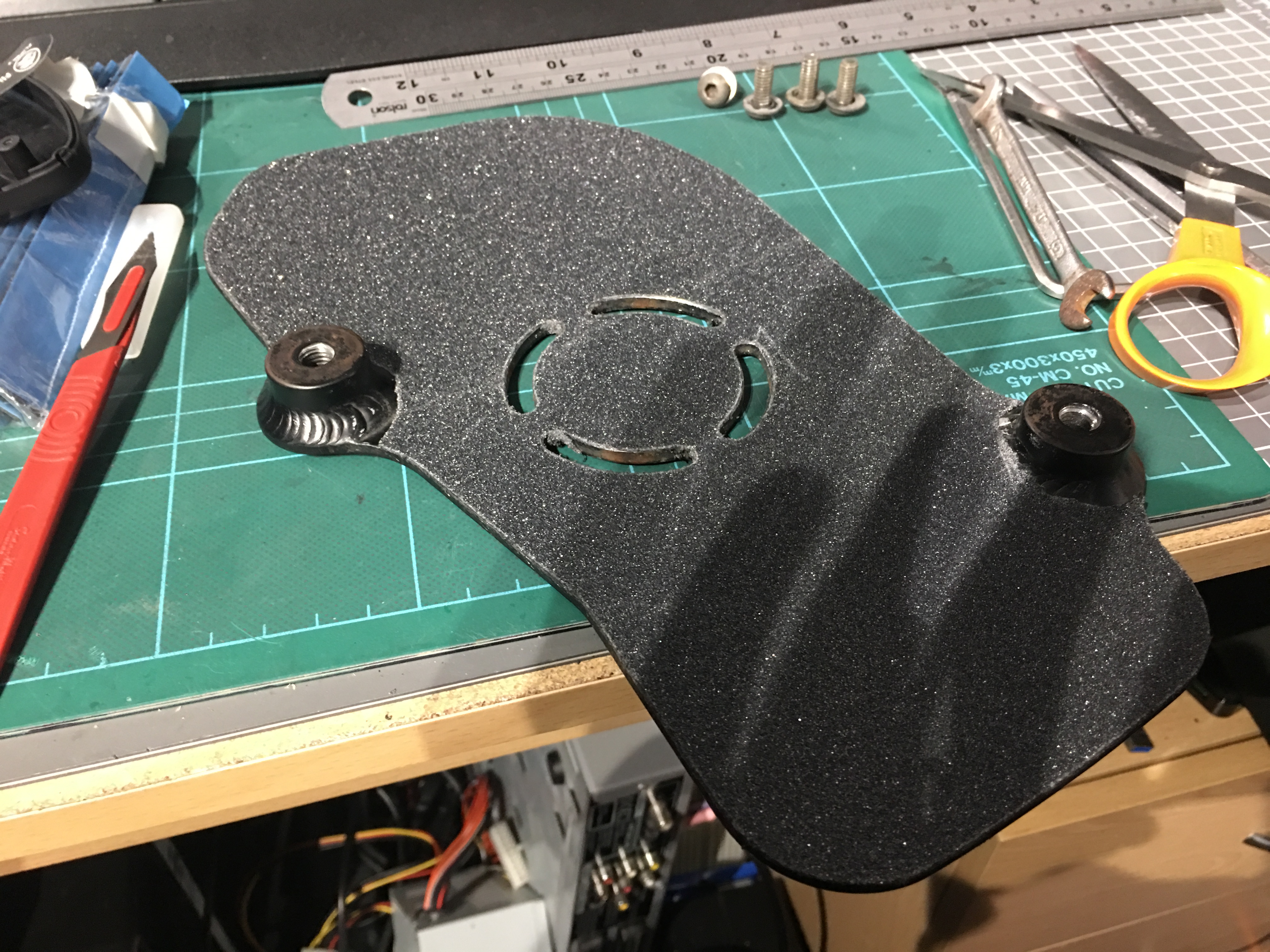
Foot plates were well worn and needed re gripping. Originally they had grip material adhered directly to the metal base. I didnt have access to that and couldn’t see why normal griptape wouldn’t work. So I sanded what remained of it, cleaned them up and papered over them. They’re a rather abstract shape, but the cut and shaping worked fine.
Fortunately the replacement pcb turned up and was working fine. Massive thanks to Nexus boards for sorting it for me. So I now finally get round to playing with throttle curves. I was keen on keeping linear braking, but the acceleration needed taming. A few forum posts recommended a -21% exponent on the polynomial curve. So that seemed like a good starting point.
I started making the ESC wiring more permanent. I spliced the receiver battery positive on to the vesc using the supplied breadboard jumper cable. I really wish this was fused, along with a few other components of this build, but if i’m going that far I’d end up redesigning the entire vesc controller, which I wasn’t keen on pursuing at this point. Perhaps sometime in the future…
The rest of the receiver was wired into the ppm port of the vesc rather than the UART port.
The goal was to have wires exiting through the vesc enclosure and connecting to the necessary external wires. The motor phases were already fine as they were, along with the hall sense wires. Vesc power cables however required lengthening. I formed some 150mm extensions using ring connectors for 8awg/10mm^2 cable.
Now was the dreaded task of fitting the enclosure lid. This proved very tight. The bottom half fit well, but the top half near the phase wires was very tight. I used some M4x20 steel pillars (originally for the wheel sprocket) and fit them to the enclosure base. Some corresponding holes in the lid then provided a method to bolt the lid down at the top. I was concerned that only bolting the top half would let the bottom half come loose, however the lid snaps into place with latching plastic clips, so the lid remains solidly in place with just the two bolts. This was even more fortunate as the cable positions within the enclosure didn’t allow for extra pillars to be included anyway !
Now all the cables needed to be inserted through glands, which are then threaded into the enclosure lid. The gland nuts had been glued to the inside of the lid before it was fitted for some extra thread. The M16 glands for the power cables and hall sensors were rather snug, but didn’t pose much trouble. The motor phases however were incredibly stubborn when trying to fit into their M12 glands. I had to drill out each M12 gland quite substantially. Some brute force, pliers, patience and a dab of wd40 eventually got them all through.
I performed another power test at this point to confirm nothing had been damaged, and was still wired correctly. No problems found, so carried on.
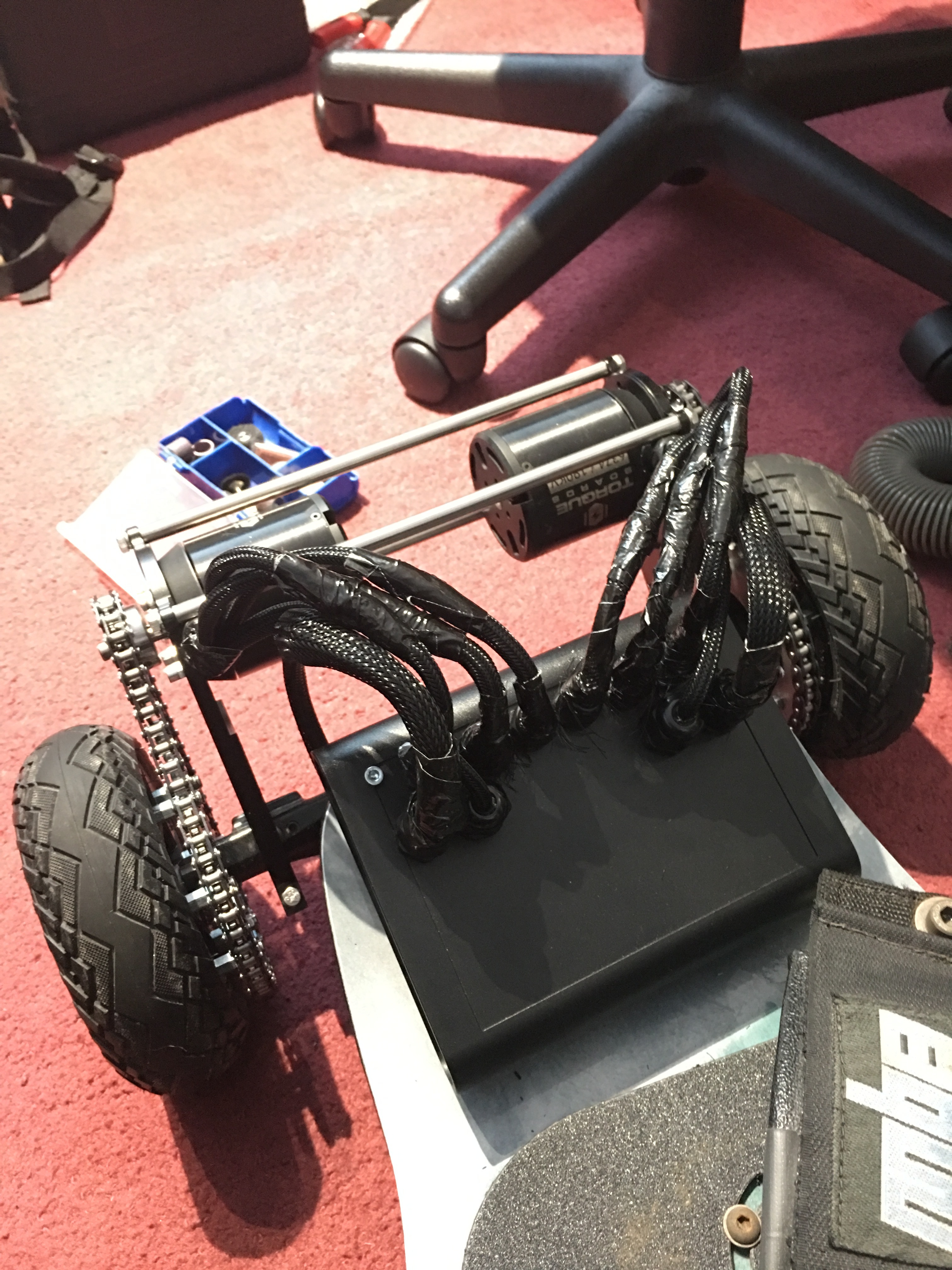
Cable management was now the biggest issue. All my previous motor testing was done with very delicate wire placement with strategic zipties, which were by no means long term. All the exposed wires were first wrapped with braided cable sleeving. This was taped off at each end to prevent fraying. The main power cables were routed appropriately between the rear truck and around the tail of the board keeping enough space between them and the motors. I then fixed them down to the underside of the deck with some p-clips and wood screws coated in epoxy.
It was obvious that the motors needed rotating 90°. The cables need to loop upwards to have enough slack to allow the board to turn. This was cutting it fine with the front motor mount brace, the wires just fit under it. Once all the phases were reconnected, the cable sleeving was permanently trimmed and fixed to the cable ends. I would have preferred to tuck this away in glands, but there was definitely no space to do that. the heatshrink also proved to be ineffective at holding the sleeving. Seems nylon is rather slippery ! The best solution I had was heating the ends to remove the frayed ends and shrink the fibers slightly. These were then duct taped down. I may revisit this in the future, but right now I just want to ride !!!
First major ride out went smoothly. I checked all bolts before riding to make sure everything was properly torqued. tyres were each inflated to 50psi. I applied some specialist molybdenum oil to the chain and cycled the motors to get the chain and sprockets properly lubricated. The loose wires for front and rear lights were taped up and cable tied to existing wires, just to stop them catching or dragging. Lights will be added shortly. Call it ‘continuous development’
This was a shakedown test to weed out all the weaknesses. First thing was motor sprockets coming loose. Solution was to apply more threadlocker to the grub screws and the motor shaft. I also filed down the ends of each grub screw, as they weren’t totally flat. So with better resistance to vibration, better contact with grub screws and higher torque applied to them, they seem to be holding fine now.
Many of my previous worries were dispelled by this ride. The chain did not catch the ground. The tyres held it away no problem. The esc enclosure didn’t catch the motor mounts or break as the deck was flexing. None of the wires got trapped, kinked, twisted or pulled too tight. Wheel vibration was not a problem, and the weights stayed on. All the work on the battery held up too. Overall I’m classing this as highly successful
I avoided getting it too wet at this point as I was planning on applying a final layer of silicone around the edge of both enclosures. This has now been done, so I hope problems don’t start surfacing !!
There are some small things I need to do immediately, like make a second blank XT90 connector to cover the exposed XT90 leads when the board is not being used. I can no longer get away with simply using a strip of electrical tape ! I also need to make another blank connector for the chargeport. I covered it with duct tape when riding, but I want a properly designed blank to do this. I would like to permanently mount the bluetooth module and battery voltage meter. I struggled to find positions for these and the bluetooth module was giving me interference problems with the receiver, so I removed it for the present. I also need to adjust the footplates. I knew these would require tweaking to optimise ride position, and now is the time to do it. I find that if I wear thicker shoes, the bindings don’t sit high enough on my feet and I end up with calf cramps very early on. i may need a new binding arrangement, or get used to thinner shoes.
The overall ride is fantastic. The board is still very flexible, even with a giant battery on the underside. I no longer feel road markings, gravel is noticeable but still poses no issue. Curbs are much more comfortaable, and roads which are far too rough for street boards and now very rideable. I thought bindings may be uncomfortably restrictive, however they are actually quite comfortable. They are crucial for turning. Even without dampers, I still need a fair bit of lean to turn.
Power is ridiculous. The throttle curves were essential for a good ride. They allow me to gently get up to speed, then shoot me into orbit when I push forward. Hills I used to cruise up at 10mph at max power, with a rapidly depleting battery are now being blasted up at 30mph, with only 60% throttle. At this point, the trucks begin to wobble, so any faster and I need to put the dampers back in, although I am quite content with 30mph for the minute !! It is significantly louder than the hub motors I’m used to, but It was still quieter than expected. First time standing on the board I popped an accidental wheelie when I nudged the throttle too hard. After scaring the heck out of me, I learned my lesson and went much more gingerly.
As promised here’s the excel file listing all the parts used on the build along with their total cost:
Note some items were purchased in excess, others were purchased and not used or are still waiting to be used, but still purchased of course !
Final thoughts at this point: I’m glad the majority of the build is over. It has taken too long for my liking, but I’m glad its mainly finished and rideable. I’ll be keeping a close eye on it and progress to rougher terrain when I’m comfortable.


 …
…


 Many sparks later two appropriate lengths of chain are connected with master links and fitted slack. The motors then slide up the mount to tighten the chain.