I had the same Feeling when reading his sentence. I think it is very rude of him!
I am just happy that he has published it so anybody can make it on their own.
I had the same Feeling when reading his sentence. I think it is very rude of him!
I am just happy that he has published it so anybody can make it on their own.
Ah. That was on a different thread. Not here.
@JTAG have you had any thoughts about controlling charging current on BMS itself? I am thinking what is a possibility for this, as I do not want to get another module to limit the current power supply for charging.
Any option to transform an external constant voltage supply either by implementing a buck or boosting converter to the BMS will limit its functionally/universality for the type of battery pack ( voltage ), charge power ( DC DC current ) and increase cost.
Or where you suggesting something else?
@JTAG how far along did the CAN stuff get? I see there’s a ‘CAN enabled’ firmware in the GitHub repo.
With a bluetooth module hooked up to a VESC, and DieBieMS CAN support (??), I could presumably just connect the new VESC tool (assuming I hack around the version checking) with Bluetooth support to the VESC and use CAN forwarding to get at the DieBieMS stats/config?
@lock yes there was a moment where I had CAN operational but after a bit of testing in combincation with two vesc’s I discovered that I had a bug where the high bus load communication generated by the vesc’s influenced the BMS firmware. I therefore disabled the CAN functionality in software to first focus on other higher priority stuff. BUT! I am now actively developing and expect to have CAN back up and running soon!
To everyone; my apologies for the lack of firmware updates and response, I was incredibly busy with other stuff. The last weeks however have been more focused to the BMS and a list of firmware features I would like to add. Once this revision is tested on my vehicles for a couple of days ill release it for all of you!
Awesome, I might order a few cables given they’ll take weeks to arrive. Do these ones (Molex Pico Picoblade 1.25mm Cable 5 Pin) look ok?
It’d be great if you could bump the VESC firmware version number it pretends to be so it’ll work with the latest VESC Tool. Main reason being the inbuilt Bluetooth support.
I’ll stop with the feature requests now  . What we have right now is a really quite nice, fully functional BMS. If you were to stop developing it and forget all about it then I’d still be happy, anything that comes later is just a bonus.
Completely forgot to mention that just pushed a new version (V0.7) of the hardware to Github, there are no amazing / spectacular new features, just three that are worthy to state.
NTC Power stage I added an option for the NTC of the power stage to be placed even closer to the switching / charging logic:
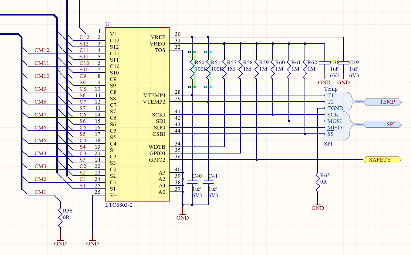
You can now chose between either of the two locations, not both :).NTC on LTC changes All previous versions that are produced of this BMS (pre V0.7) contain an error in the pullup resistor value of the NTC’s. I mistakenly assumed that the LTC would be capable of driving a dual 10k pullup / NTC combination from its internal voltage regulator. After me attempting to implementing the battery NTC and reading the datasheet of the LTC I learned that this impedance is to low. These are the resistors:
And in the schematic:
As seen the new pullup values should be 100kOhm. You will only need to change these resistors if you plan to implement the external temperature sensors for the battery pack.
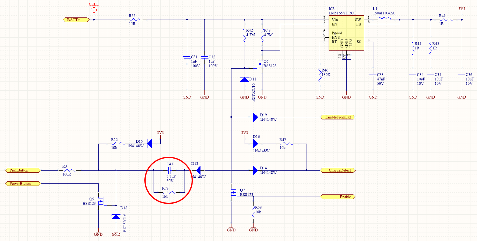
Power switch options In a few applications (like my electric scooters) I have a main “ignition” switch that does not behave as a pulse switch but like a continuous switch. I really started to desire supporting a continuous switch as a power switch but struggled with thinking of an implementation where the BMS would still be able to power itself completely down in an extreme condition (like forgetting to power it of or when the battery is extremely empty -> below hard under voltage level).
All versions of the hardware (with the upcoming new version of the firmware) will support the continuous switch as a means of power on/off however only from V0.7 and up will the BMS be able to turn itself completely off.
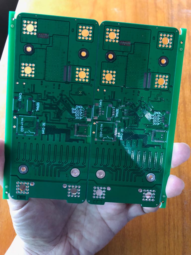
The hardware changes on the board are here:
And the schematic changes are these:
It is a high pass filter construction but with the benefit that there is minimal leakage current when a switch is closed.
This is the connector used on the PCB:
https://www.molex.com/molex/products/datasheet.jsp?part=active/0532610571_PCB_HEADERS.xml
So yes de description sounds good but something tells me that the FRSky connector style is different (but the drone hobby is very old so my memory could be wrong  ).
).
Hi all,
I will make small batch of v0.7 (20pcs). Will keep 5pcs for myself, so 15bare pcb or finished pcba up for grabs after we tested 2pcs successfully in the coming weeks. PM me if interested, I will provide more details.
Thank you Danny for creating the project.
Sam
Disclaimer: Nu functionality yet! But I am really close to start and implementing that :). I am impressed by all the amazing work Benjamin had put in the VESC tool and the tools he made to adapt the tool. I am first going for VERY basic functionality like configuring most of the important stuff and later on I will add stuf to upload custom pictures to the OLED display.
And OFCOURSE it will be opensource  !
!
I have some experience with SOC algorithms that are more complex than the simple coulomb counting method.
Is there anyway you could send me some data from the SD card? All CV, current, Temperature (?), motor commands, etc.
I would start working on this after may 15th, so no rush.
Also, I’d like to build the BMS. At least one. Would anyone be willing to sell me a couple of PCB? If you have some that are already populated or have spare parts, it would be even better. I’ll pay of course.
Hi, I have a Hobby King 6s BMS that I am going to charge my 6S batteries with. How much power do I need to give the BMS to have it charge my batteries. Thanks
Where did you order PCBs from?
I normally order trough Multi-CB, but recently discovered JLC PCB makes decent enough PCB’s as well!
It seems I would need a Level3 account to create the groupbuy account.
I hope Danny don’t mind me starting a sale here. Please keep all inquiries to my PM to avoid messing up this thread. I will try to create a separate post also, but not sure if the admin allows for sales post in other categories.
I will assemble and sell 15 pcs of DiebieMS v0.7.
The deliverable are as followings: 1 x DiebieMS v0.7 assembled. (SD Card and RF module NOT mounted). Components I have stayed true to the original design. 5 red and 5 black x wire connectors (non-crimped) for battery and VESC 4x. 1x Male 16P connector 20 pcs non-crimped terminal for balance cables (some are spares) 1x Momentary switch 1x OLED 0.96 Display 4x single end male connector with cable (JST 1.25mm 5p, 10mm) (Display, switch, canbus) 1x single end male connector with cable (JST 2mm 4p, 10mm (VESC side can bus) 6x M5x14 spacer screws 1x 80A Fuse
Asking for 120USD/pc shipped to major cities around the world via Hong Kong Post with tracking Number. (~8-10 days) destination tax and duties not included. PM if interested, I will create PayPal invoices. Will take ~2 weeks for completion, I have most of the parts already.
Canbus test (*note I am using Ackmaniac firmware on my vesc, that’s why there is a warning)

Current list: @uigiroux (1x Confirmed) @Giga (2x confirmed) @DeathCookies (3x confirmed) @PXSS (2x confirmed) @chsknight(2x confirmed) @Rene(2x confirmed) @Jumpman(1x confirmed) @bflan(1x confirmed) @PatRocks (1x confirmed)
All sold, please message me you email for PayPal invoice if you haven’t done do. That was quick .
I want to let you all know it may be a while until I can make another run with this type of quality built. As a manufacturer, I was able to get limited quantities of the parts. But my suppliers would likely impose a minimum quantity for my next request. It won’t be easy to make another batch unless I get “a lot” of orders. So don’t miss the chance to pick one or a few of these beauties up.
A little background about myself. I own a electronic factory in China (smart home). So I was able to use my resources to make this run possible.
Finally, I must thank Danny for the design. Really awesome BMS.
You would have to make a new thread offering this for sale. But the post is related and on topic with the title.
If there are still two left I would love to get in for 1.
Let me know, thx.