Oh man. This hack is even more epic than the hack I posted over in the other thread  . I love it!
About @raphaelchang 's BMS, perhaps is there someone n the shadow working on it ?  I’m mean, “in the shadow” is even not true because he keeps people updated and asked for support
Anyway, the VESC Tool trick is an amazing idea. I keep this idea in the corner “in case of”. Really nice work !
I really hope, i planned to help put things moving, but since the connection for debugging is only working on mac i’ve put it aside and ordered a cheap BMS from aliexpress
@JTAG do you have the schematic somewhere? the link is not working and i couldn’t find on GitHub
thanks
No worries.  I’m a early beginner into C coding so it’s a big amount of work to train myself (reading books or studiyng other codes like @JTAG or Vedder’s’s one ) and to gain knowledge (or remembering as I had some lithium batteries courses at university) about the way to manage charging/balancing.
ATM, I wrote A LOT of code (including charge/balance storage, CAN bus with VESC, UI, SoC, voltage SAG calculation and so on) but I’m still in the process of building a bench to try all this fresh and non-debugged code with safety.
Sorry JTAG for this off topic. 
Should we be using the IRFS7730 instead of the IRFS7530 found in the latest BOM?
There’s a serial port under the board. Would it be possible to wire up one of those HM-10 Bluetooth modules?
the board has can bus, so yes
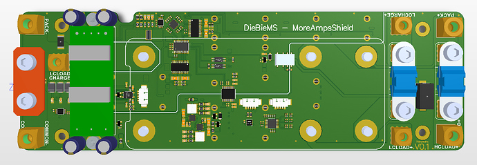
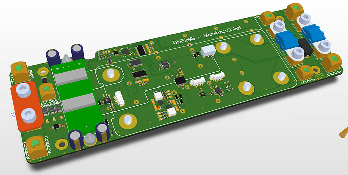
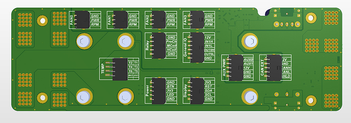
By a customer’s request; a shield that adds 6 temperature sensors, a DC - DC converter (for 12V on the can bus), 4 fans with rpm control, buffered IO, relay driver, additional pre-charge method and shunt to allow currents up to 250A  .
.
This will be perfect for applications that require a bit more power or “MoreAmps”  .
.
Once the design is tested and my customer is OK with it ill opensource as well.
Superb thanks for your contributions @JTAG
I’m hamfistedly putting together a small case for the bms, I’m almost certertain that I should make room for an anti-spark there too? My electrics are in vesc cases by @Kug3lis and cells in nese cases by @agniusm
No need for anti spark, it is all build into the BMS, the pre-charging and the switching ![]() .
.
Oh man so cool thanks
Fancy!
XLR can be used as a charging plug, a friend of mine did it and it worked fine.
It is unclear to see but the balancing leeds might need some more room to get into a right angle radius, this gets me as well sometimes.
I decided to make 2 holes and n front of the balance lead port, I will split the leads into two silicone tubes running up the ‘spine’ of @agniusm’s packs
The xlr panel was too large, by itself it would raise the enclosure height another 5-10mm so reverted back to a laptop port 5.5mmx2.5mm iirc, the thread for this should be about 10mm so that’s what I’m printing right now HNY!
Ps: all being good once design is acceptable I will publish and link here my feeble attempt 

Will be delayed prototyping as printer has a bed problem and have to leave for work tomorrow so HNY all will have something by next weekend
If delay is bad I picked up the initial case design on thingiverse
I managed a print of the bottom shell before my printer crapped out…too small, I need to work in scaling and fixing the problems
i.e. Moving the holes for the balance wires closer together
Added can comms port
Changed xlr port to 10mm threaded hole
12mm switch threaded hole
It glows in the dark…crappy iPhone
Quick question…
When wiring up do you connect the main battery +/- then the balance cables (or vice versa)?
I know some BMSes are a little sensitive to the order in which this is done.
DO NOT SCREW THE CONNECTION UP!! I did it and had to replace a couple resistors. To be 100% sure, double check with the multimeter: you should see increasing voltage from c1 to c12; this way the diodes can do their job.
Thanks for that figure. I was 90% sure that was the way it was intended, nice to be 100%  . And yes, I’ll definitely go over it with a multimeter first.
BUT, when I’m connecting the wires to the BMS should I first connect the battery main +/-, then the balance connectors? It possibly doesn’t matter with this BMS, but does with some others.
Another question too… I wasn’t planning on using the temperature sensors right now; can I simply leave T1, T2, and the “GND FOR NTC’s” disconnected? Or do I need to hack it and include some conventional resistors I have lying around (ohms?)


