@JTAG: the 915MHz band is only in America a ISM band -> not allowed to use it in the rest of the world except you have a HAM licence other than that - nice BMS!
For other countries there are other module of the same type:
https://www.anaren.com/air/products/air-proprietary-rf-apps
All have the same footprint.
I personally wont be producing / selling the BMS on the short term, maybe in the future  .
.
There might appear other that produce it like these:
@JTAG quick question, will the bms allow to charge a pack with higher voltage than the charger? Like if i want to charge 12s pack with 25.2v charger ?
Nope, the charger has to have a higher (about 3V isch) voltage than then battery, preferably at all times. The BMS does not boost the voltage.
Any 48V PB battery charger will do. 48V battery charges (all will be oriented to charge 4 lead acid batteries in series) will have a high enough open clamp voltage to trigger the charger detect mechanism on the BMS. This is what I use on my E-Scooter.
The minimal open clamp voltage to automatically detect the charger with a full battery will be 12*4.2+3=53.4V. A voltage between 53.4V and 60V will be fine.
Or 3.6*12+3 = 46.2 if your batteries max out at 3.6v? Hoping this is modifiable via settings 
Yes, exactly! All voltages are configurable.
In my example I assumed the most common li-ion isch voltage. What chemistry do you use?
Cool, this was one of the main reasons I really liked this BMS; it’ll support my current chemistry and any others if I change my mind in future. Battery pack is a 12S2P A123 26650 LiFePO4 setup.
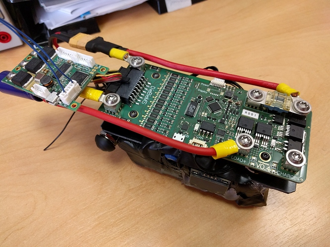
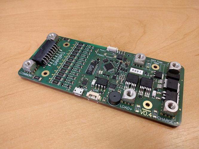
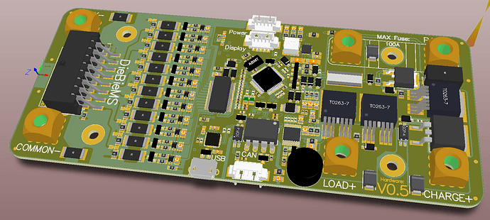
Ok, I finally had time to build and evaluate my latest design, I found a very small improvement and fixed it right away (I had the wrong value resistor next to the NTC) in the design. So for everyone that wants to make a DieBieMS; you are good to go!
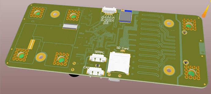
This latest revision has an NTC close to the switching logic (to intervene with possible overheating of the switching logic) and an optional Anaren transceiver that could be used as a receiver for a remote  (I really like this optional feature).
I tested the NTC and the communication to the transceiver and they both seem to work.
This board is not fully populated, I couldn’t find the parts for the sections of the board with missing parts (TVS diodes and the display connector), those sections however did not change and were already proven to work in the previous versions.
I couldn’t find the tool to insert the press fits all the way but really wanted to start testing. Once all components are in and I pressed the pressfits all the way ill post a pic (again, this has no influence on the functionality).
Thanks for everyone’s patience so far!
In my latest design I use the 7730, I might have used the other FET in older designs/prototypes but the 7730 should be in the new.
What is the benefit of having a F1 instead of the F4? You have freedom now to implement almost everything you want. In the future features might be added ( like a receiver as on my latest design ) and maybe logging (also possible on my latest design ). The added cost and power usage was in my opinion negligible compared to the value of more computational power (but that is just my opinion, I might have overlooked something).
Thanks for analysing and help!
This was a reply in this topic:
I wil try and aim to keep most of the technical information here else everything might get scattered around.
That makes sense, similar reason to Vedders choice of the F4 for the VESC. And the only benefit of the F1 or other smaller microcontollers was price and power consumption but for this application I suppose it doesn’t really matter. Though on that topic what is the standby power of this BMS? Im assuming the F4 has a very low power sleep state and thats what its in most of the time yes? Anyways thanks for responding!
Look at the schematic, once powered down the whole board except for a couple of multi meg ohms is disconnected. The sleep power of the MCU doesn’t matter since its completely disconnected from the batter  .
.
When will the next batch of BMS’s start up?
Hi Everyone!
I have been crazy busy working on more projects than I can handle  . The resent developments with the group buy, some of my friends I sold a BMS to for their skateboard asking to configure / customize it and a personal project (efoil) had me to focus for the last two days on implementing a basic way of status reporting and customizing the BMS trough a UI.
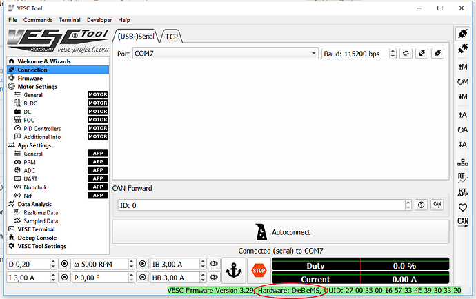
And with the help of the world of opensource I represent to you; a crudly simple way to configure the BMS (for now). Of course I (or we  ) will be realising a decent UI but for now this should provide basic functionality:
The firware version is incorrect, but I have to set it like this to trick the VESC-Tool to allow me to use the terminal.
I implemented the communication style of the VESC, this will make it crazy easy to (in the future) configure all esk8 electrical components over the same CAN bus, for now only USB is supported (no CAN, no firmware upgrade, no UI yes) in collaboration with the VESC-tool and its terminal. I am eager to start implementing firmware upgrade and CAN functionality but I simply was unable to finish it on time for the group buy to start shipping (sorry guys  ).
).
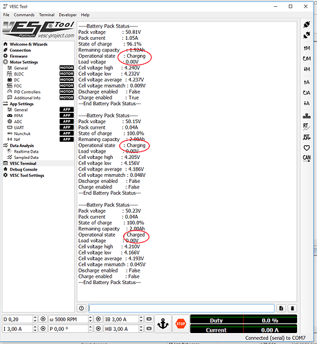
I was however able to implement cell voltage status report generation over terminal:
Battery summary report:
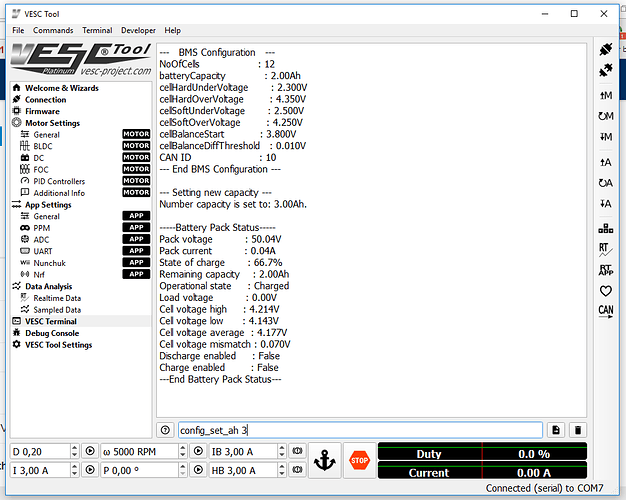
Change settings:
Like: pack amp hours cells in series soft and hard under and over voltages (determines the (dis)charge enable moments and error states). can id (for the future) cell voltage threshold to start balancing cell mismatch balance start threshold
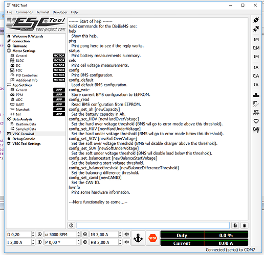
And reports a help info block:
More to come! Thanks for you patience everyone  .
.
@JTAG Would be possible to port your firmware to @raphaelchang BMS? At least part of it? If you say so I think I will try that since Raphael vanished and left us with non working boards


