I’d like to contribute too, but this seems out of my league. I guess I could offer sutures if things get out hand 

2 Likes
@JTAG I’d love to test a couple of these out.
For science!
You are raising the bar on what can be done DIY. I just want to support what you do!!
2 Likes
Me too. I would like to buy some for test purpose too
Ditto. This means I will probably buy some batteries and a spot welder as well.
I think I may have a problem. Hi, my name is Korry and I am an esk8aholic.
1 Like
@JTAG this is looking so good! I’m definetly also interested! your work is taking esk8 to the next level, keep it up man 

Thanks guys (as I assume there are mostly guys around here)!
Once we are confident everything operates safely we will be offering complete prototype boards (very limited). Functionality will gradually grow since up until now it seems I will have to make the software as well  ( any volunteers? It will first only be embedded software and in the future something with a chrome app “cleanflight” UI style ).
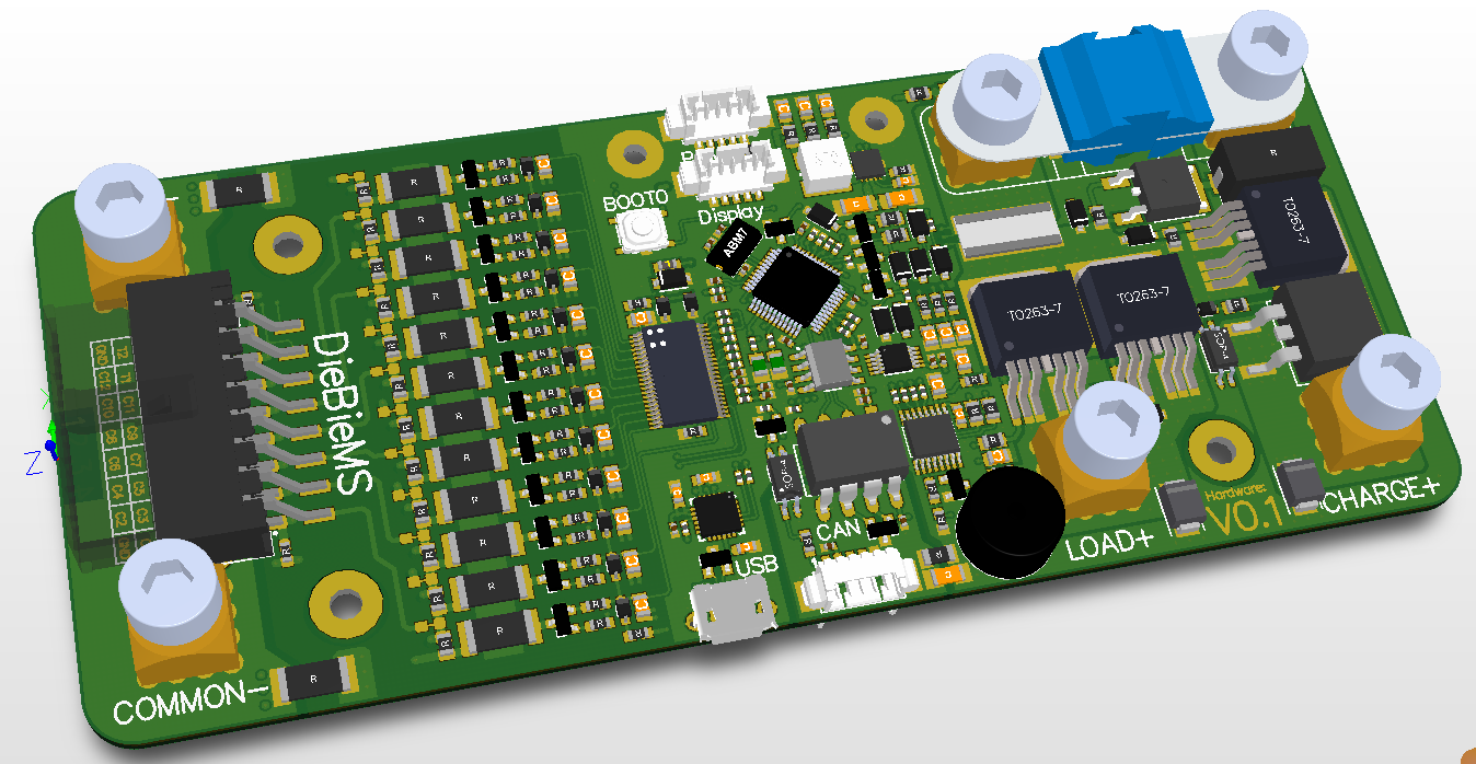
In the meantime today I was able to finish the rough routing, tomorrow ill do a little tweaking, polishing and designrule error solving and then its up to the PCB fab !


I did a minor update to the schematic, we should now be able to detect if the main fuse is broken / has failed. Lets hope that this all works!
Somehow I completely missed all the request for dimensions :o. The dimensions are:

And the height approximately 15mm including the bolts to mount the wires. This can be lowered if you find a different way to bolt the cables to the enormous press fit sockets xD.
If you wanna have a play with it in 3D, you can import this STEP file into for example Solidworks.
6 Likes
Nice this is so exciting  this is great work man thank you !!

9 Likes

When can I get one?
Looks fantastic! I’d definitely be available and interested to be a tester
Put me down for one!!!Man that is talent to just whip up a bms in your spare time, while your at it just add dual vesc’s a reciever and charger if you come across some more spare time. That would be a nice plug and play system…
Put me down as a tester.
1 Like
I’ve been following this and literally can’t wait… This is going to be sweet
1 Like
My god this is awesome. I would love to try this out ASAP.
This is epic. I’ve also been following the progress of this BMS. Can’t wait to see what it looks like.
Thanks :D! But calm down guys, its still a prototype  . There is still some hardware verification to be done + some software to write (luckily the latter can be very simple at first).
In comparison to our hacky VESC setup:

In the future when the VESC 5.0 / 6.0 (whatever it is called) is matured I might squeeze VESCs + caps in the same footprint as the BMS allowing for a nice and compact DIY buid ^^.
16 Likes
I’d like to jump on the list for one once their available, I can also try my hand at hardware debug (just got out of school as an electrical engineer, gotta put it to good use!) if needed, slightly lacking tools right now though  .
.
Not sure if it’s mentioned above, didn’t see it the last time I ran through, but what’s the current rating ? Also thoughts on how to handle that directly on the PCB. I.e trace widths etc
@JTAG knows what he’s doing, i have my doughts about the 150A fuse on the silkscreen. But i’m sure it can handle a good amount of continuous current.
ohh yeah his work is awesome, not doubting that, i’ve been starting to work with some higher current designs and i’m looking for some opinions from others.