I just read the thread about the metr.pro upgrade, just awesome progress!
But now, the VESC is kind of the CAN master when using metr.pro and need to be powered on before the communication gets active. I prefer not having my VESCs energized for an hour or longer during charge.
Does the D.B.MS forward CAN data? if so I would be able to connect the metr.pro to the BMS serial port instead of to the VESC.
This would open up some possibilities:
The VESC would not have to be powered-on to monitor the charge process or battery state.
Metr.pro would be able to send push messages when charge is done or if there is an issue
With push-2-start I would be able to check my battery state before rolling off
At some point the BMS could also store VESC logging to the SDcard.
Right, I’ve just bookmarked those because @JTAG had mentioned them somewhere.
Additionally, I believe you need an extra 3v on top of your nominal voltage for your charger, so having the adjustable Voltage and Amperage so those are nice for that flexibility
Metr.pro is designed for VESC and works great for logging and configuration!
They are currently integrating DieBieMS features (state of charge with fancy animation), no configuration page for DBMS (jet?)
you can still do so via the terminal and CAN fwd (ID:10) in the app.
I am not really familiar with switching losses, heating and stuff. But in my understanding a buck converter is only a PWM switch with additional smoothing by caps and coil. And for buck converters efficiency rises for low voltage differences (vin vs vout). So if I am right, the losses at high dutycycle switching should be small and from ~55V to 36V you are always above 65% duty, for Lipos even above 80% duty.
And even if there is some heating, you could always regulate the charge current down according to the temperature of the closest NTC. So you do not have to have a CC/CV powersupply but a CV is sufficient (like the cheap ledstrip powersupplys)
So what do you think, could a simple software 40kHz PWM regulate the input current?
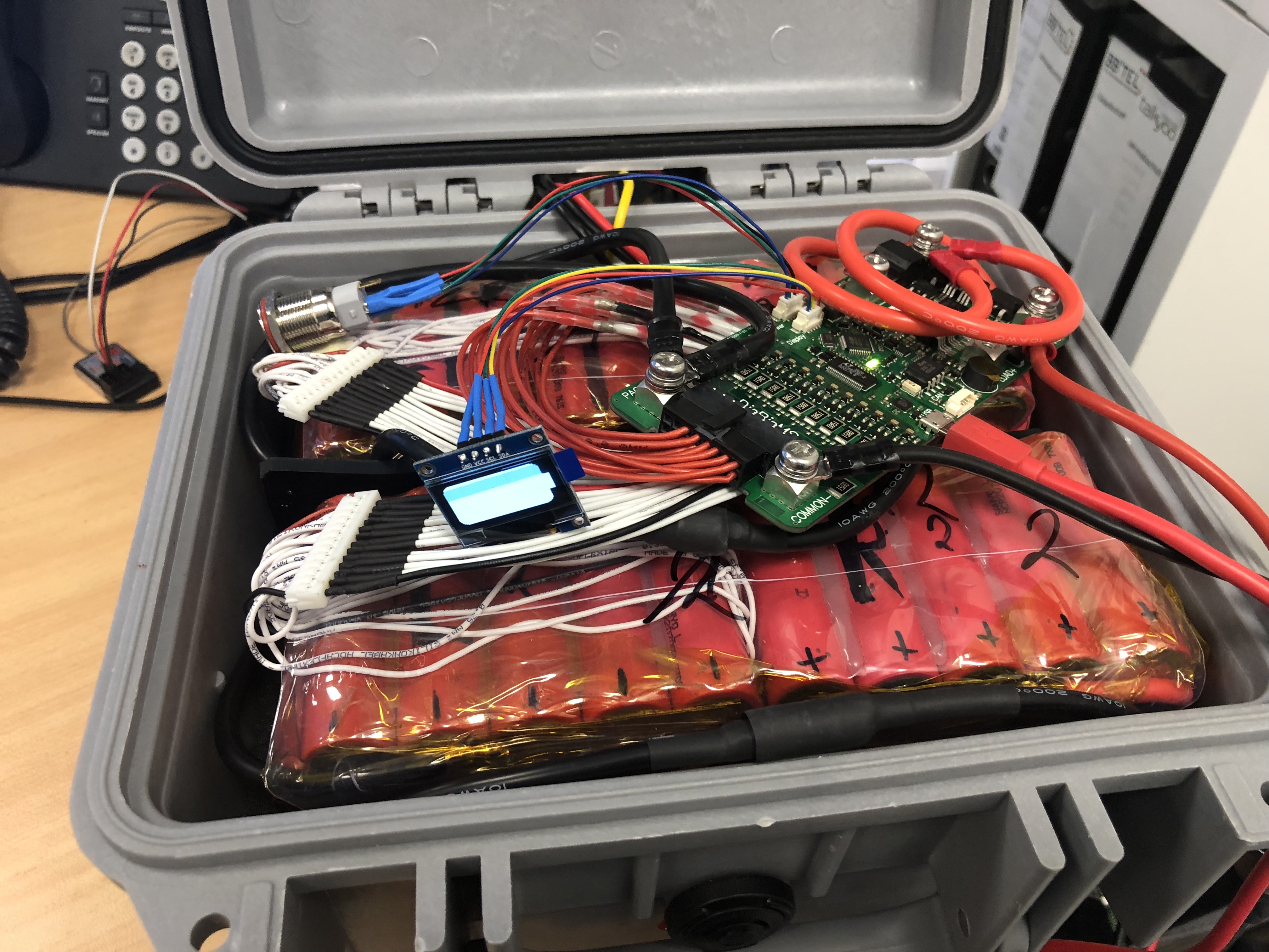
Just attached the DieBieMS to my 2 x 12s5p == 12s10p.
The balance cables and PACK +/- are connected.
DieBieMS does power up. HW V0.7
DieBieMS-Tools can connect to the MS states FW 0.16
FW Upload does work.
But after reboot - it is still 0.16
Can NOT read / NOT write values with the DieBieMS-Tool
only Terminal commands.
Strange “State of charge” - 1.5% - at 12s with 48.97V it should be above 90%
What am I doing wrong?
Please find all data below.
------- BMS Info -------
Firmware: V0.16
Hardware: V0.3
Name : DieBieMS
UUID: 33 00 3E 00 10 57 34 56 36 30 33 20
------- End BMS Info -------
----- Cell voltages -----
Cell voltage 0 : 4.088V
Cell voltage 1 : 4.089V
Cell voltage 2 : 4.080V
Cell voltage 3 : 4.089V
Cell voltage 4 : 4.089V
Cell voltage 5 : 4.089V
Cell voltage 6 : 4.089V
Cell voltage 7 : 4.088V
Cell voltage 8 : 4.089V
Cell voltage 9 : 4.089V
Cell voltage10 : 4.089V
Cell voltage11 : 4.083V
Cell voltage high : 4.089V
Cell voltage low : 4.080V
Cell voltage average : 4.088V
Cell voltage mismatch : 0.009V
----- End Cell voltages -----
-----Battery Pack Status-----
Pack voltage : 48.97V
Pack current : 0.02A
State of charge : 1.4%
Remaining capacity : 0.57Ah
Operational state : External (USB or CAN)
Load voltage : 0.00V
Cell voltage high : 4.089V
Cell voltage low : 4.082V
Cell voltage average : 4.088V
Cell voltage mismatch : 0.008V
Discharge enabled : False
Charge enabled : False
—End Battery Pack Status—
Sorry for the lack of response from me lately I have been very busy. But also busy on adding new features to the BMS and the interface. The most important thing I am working on is a self test feature to test the BMS after production and changing the hardware to add test pads for a test fixture.
I will soon take time to answer all unanswered questions soon!
And for the last question, I am sorry that might indeed be a bug . I still have to automate incrementing the firmware version on every place in the firmware automatically.


 . I still have to automate incrementing the firmware version on every place in the firmware automatically.