Right, I’ve just bookmarked those because @JTAG had mentioned them somewhere.
Additionally, I believe you need an extra 3v on top of your nominal voltage for your charger, so having the adjustable Voltage and Amperage so those are nice for that flexibility
What do you mean? You are not able to configure VESC via metr app?
Metr.pro is designed for VESC and works great for logging and configuration!
They are currently integrating DieBieMS features (state of charge with fancy animation), no configuration page for DBMS (jet?) you can still do so via the terminal and CAN fwd (ID:10) in the app.
1 Like
@JTAG didn’t see it anywhere, but would this work with Hobbywing Max6 ESCs and off the shelf Turnigy cell packs? Do I need to have a Vedder based ESC?
Any update on this project?! Looks like it would be amazing for some of us 
What about simple PWM?
I am not really familiar with switching losses, heating and stuff. But in my understanding a buck converter is only a PWM switch with additional smoothing by caps and coil. And for buck converters efficiency rises for low voltage differences (vin vs vout). So if I am right, the losses at high dutycycle switching should be small and from ~55V to 36V you are always above 65% duty, for Lipos even above 80% duty. And even if there is some heating, you could always regulate the charge current down according to the temperature of the closest NTC. So you do not have to have a CC/CV powersupply but a CV is sufficient (like the cheap ledstrip powersupplys)
So what do you think, could a simple software 40kHz PWM regulate the input current?
Hey Guys,
I need you help. @JTAG
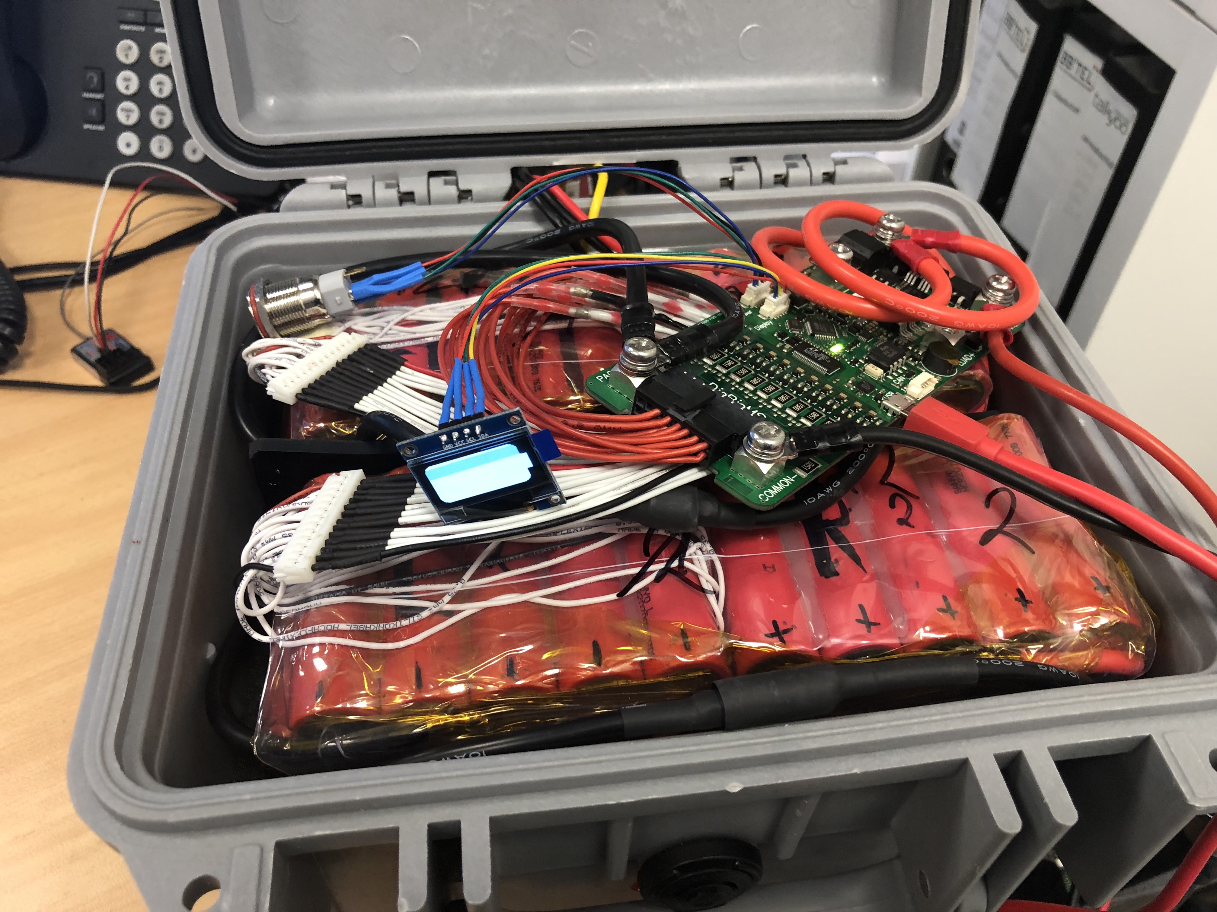
Just attached the DieBieMS to my 2 x 12s5p == 12s10p. The balance cables and PACK +/- are connected.
- DieBieMS does power up. HW V0.7
- DieBieMS-Tools can connect to the MS states FW 0.16
- FW Upload does work.
- But after reboot - it is still 0.16
- Can NOT read / NOT write values with the DieBieMS-Tool
- only Terminal commands.
- Strange “State of charge” - 1.5% - at 12s with 48.97V it should be above 90%
What am I doing wrong?
Please find all data below.
------- BMS Info ------- Firmware: V0.16 Hardware: V0.3 Name : DieBieMS UUID: 33 00 3E 00 10 57 34 56 36 30 33 20 ------- End BMS Info -------
----- Cell voltages ----- Cell voltage 0 : 4.088V Cell voltage 1 : 4.089V Cell voltage 2 : 4.080V Cell voltage 3 : 4.089V Cell voltage 4 : 4.089V Cell voltage 5 : 4.089V Cell voltage 6 : 4.089V Cell voltage 7 : 4.088V Cell voltage 8 : 4.089V Cell voltage 9 : 4.089V Cell voltage10 : 4.089V Cell voltage11 : 4.083V Cell voltage high : 4.089V Cell voltage low : 4.080V Cell voltage average : 4.088V Cell voltage mismatch : 0.009V ----- End Cell voltages -----
-----Battery Pack Status----- Pack voltage : 48.97V Pack current : 0.02A State of charge : 1.4% Remaining capacity : 0.57Ah Operational state : External (USB or CAN) Load voltage : 0.00V Cell voltage high : 4.089V Cell voltage low : 4.082V Cell voltage average : 4.088V Cell voltage mismatch : 0.008V Discharge enabled : False Charge enabled : False —End Battery Pack Status—
— BMS Configuration — NoOfCells : 12 batteryCapacity : 41.00Ah cellHardUnderVoltage : 3.400V cellHardOverVoltage : 4.250V cellSoftUnderVoltage : 3.300V cellSoftOverVoltage : 4.250V cellBalanceStart : 4.100V cellBalanceDiffThreshold : 0.010V CAN ID : 10 — End BMS Configuration —
2 Likes
OK @JTAG - read the whole thread again and found the part where you describe the bootloader_jump command.
Now it says v0.21 in the DieBieMS-Tool - but the LCD states v0.17 at boot.
Is this normal?
1 Like
Hi guys!
Sorry for the lack of response from me lately I have been very busy. But also busy on adding new features to the BMS and the interface. The most important thing I am working on is a self test feature to test the BMS after production and changing the hardware to add test pads for a test fixture.
I will soon take time to answer all unanswered questions soon!
And for the last question, I am sorry that might indeed be a bug  . I still have to automate incrementing the firmware version on every place in the firmware automatically.
7 Likes
DieBieMS is now managing 12s10p of 20700B.
Wow - this is just the coolest BMS around! Thanks @JTAG from Hamburg.
9 Likes
you can maybe still get one here
1 Like
Was actually referring to the “More amps shield” that he was (or is) developing, Thanks though!!
It’d be great if someone would do a large run to keep these in stock. I don’t need one right now, but in the future it’d be great to have to option to buy it outright instead of waiting on a GB. I could see this becoming the new standard if it we’re more available.
2 Likes
I made extras with this run.
Sam
2 Likes
@JTAG didn’t see it anywhere, but would this work with Hobbywing Max6 ESCs and off the shelf Turnigy cell packs? Do I need to have a Vedder based ESC?
you dont need a vesc, but some of the functions will not work without it
Thank you so much for this great work. I’ve been loosely following your progress from the beginning and I’m catching up now on what I’ve missed lately and it’s a lot.
I have 2x the V0.8, and reading back, I saw you mention the MoreAmpsShield last December (2017). I haven’t seen anything about this since then. Do you have any idea when I could expect more from this?
I’m debating what to do right now as 80a is just not enough for me (was trying to do 200a+, as I run 4wd). I read before the plan was to allow this to support 140a in theory as it is. Have you tested this yet? Is there a 140a fuse that will fit nicely?
Charging wise, limit is 15a, correct?
I’m a bit confused on the charge current. You said to detect charge, it needs to be 3v above pack voltage? So it won’t detect a charge if say my pack is at 49v and the charge current is 50.4v? Do I need to set it to 53.4 then?
I’m still confused about the canbus connection to the vesc, but hopefully I find something that clarifies this soon (still not done reading all of the topics and every message, soooo much to read, haha). Do you just need to connect CAN L BMS -> CAN L VESC and CAN H BMS to CAN H VESC?
The manual would be great. I might through something together in the mean time for others, because it’s not efficient for everyone single person to read all of these lengthy threads. Already been about 4 hours and I still have at least 2 more to go through.
Thanks again for this amazing piece of work. Would love to use the full power potential of my setup though (200a+, could even set each vesc to 80a for 360a total in theory). I think it’s worth limiting my power output for the time being and using this instead of not using a bms, since I’m now using a 25ah lipo pack. But would love to get this running at higher amps.
3 Likes
In general, the ESC should have no effect on the bms. They are separate, compartmentalized systems. This bms has a canbus port, which the vesc also has, and it seems there’s some firmware stuff being implemented so the VESC and BMS can be blended together nicely. But this is the icing on the cake.
Personally, I would recommend a VESC, especially a VESC 6. I’ve tried pretty most vesc’s out there and the only ones standing still are the official VESC 6 (damn you Frank for charging so much!!! I know how cheap your BOM is now!) and the Axle and Chaka Vesc 4.12’s. It pays in the long term to use quality parts (remember, electric skateboarding can be deadly, especially if you experience electrical failures at the wrong time).
1 Like