Hey everyone. This will be my first “build log” here. I figured this would probably be the best place to introduce myself. My name is Dylan, I’m 25 years old and currently reside in Northern California. I’m a Mercedes Benz mechanic by trade(going on 6 years now). I’m certified to work on multiple Hyrbid/full electric models that we sell(pretty recently, MB is just dipping their toe in the electrical game at this point).I am by no means an electrical engineer, but I like to think that my experience gives me a small leg up in this hobby I have taken on. Iv’e been lurking around here for the better part of the last year posting in other sections, and just soaking up info. Anyway, enough about me and onto the battery build.
I have estimated that I have over 6,000 miles on this CGT battery, and at almost 400 charge cycles this battery has seen its better days. It was a junker battery to begin with, and the range was diminishing with every ride. I decided it was time to build a new pack, and I wanted more range than before for sure. I really want to keep the remote/esc setup because I don’t wanna just throw it away and have to buy two vescs(I’ll save that for my custom build). To do this, all I have to do is keep the evolve bms and wire it up to my new pack.
When all is said and done I should have a 10s5p 15AH pack ![]()
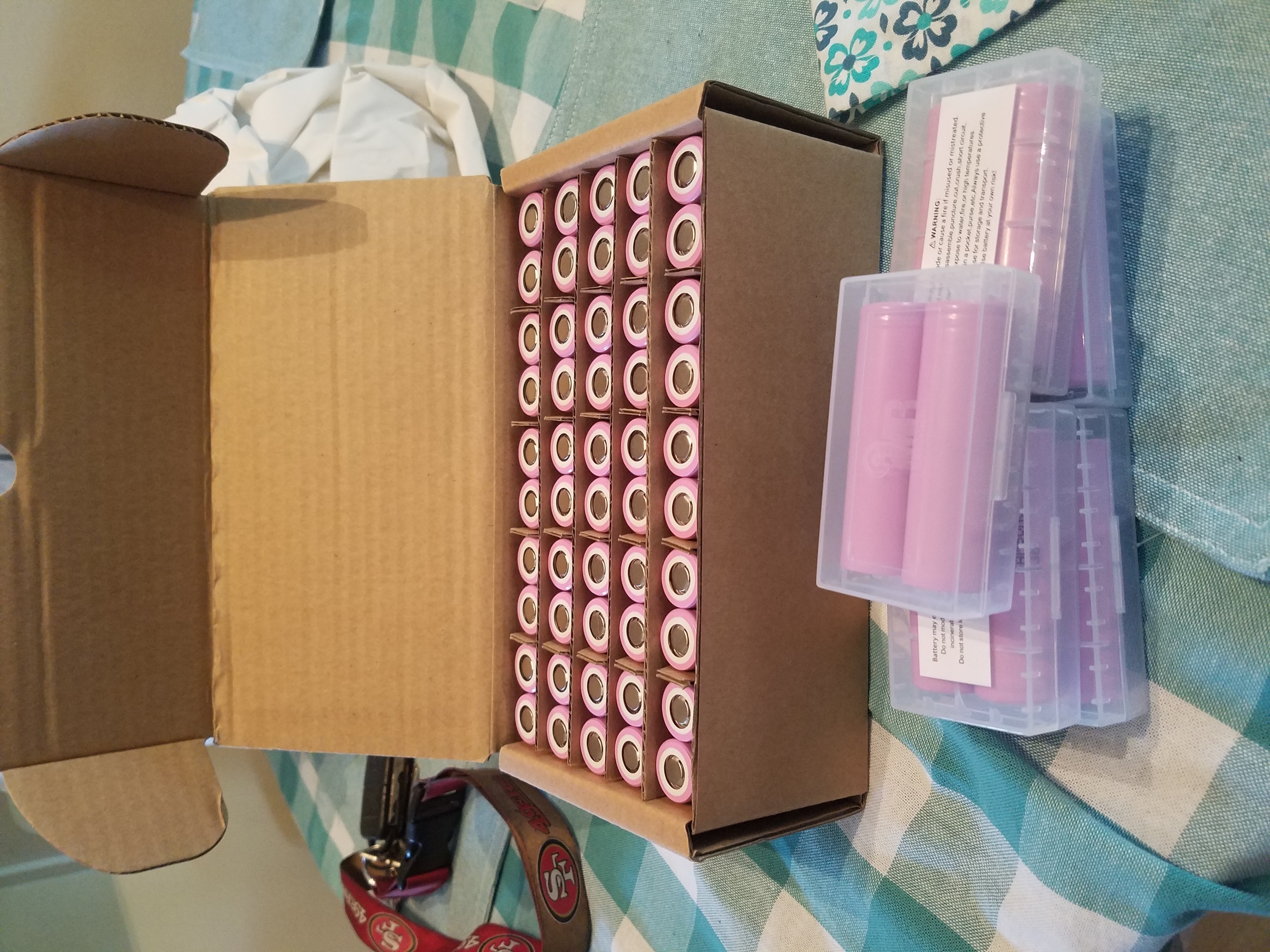
I started by ordering 60 of these Samsung 30Q batteries(50 for the build, and 10 extra for when I inevitably mess something up):
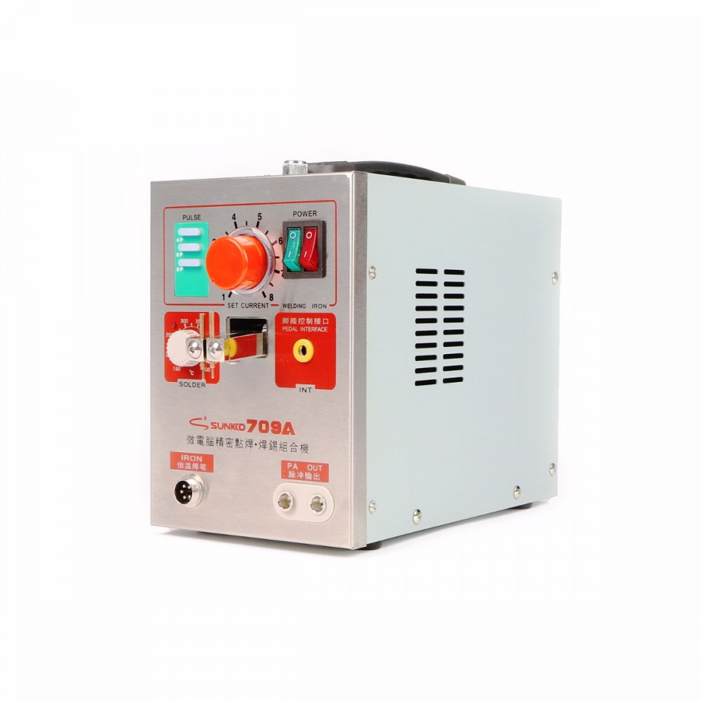
And then I ordered the Sunkko 709a(fyi i wish i bought the arduino kit instead, but this did the job fine):
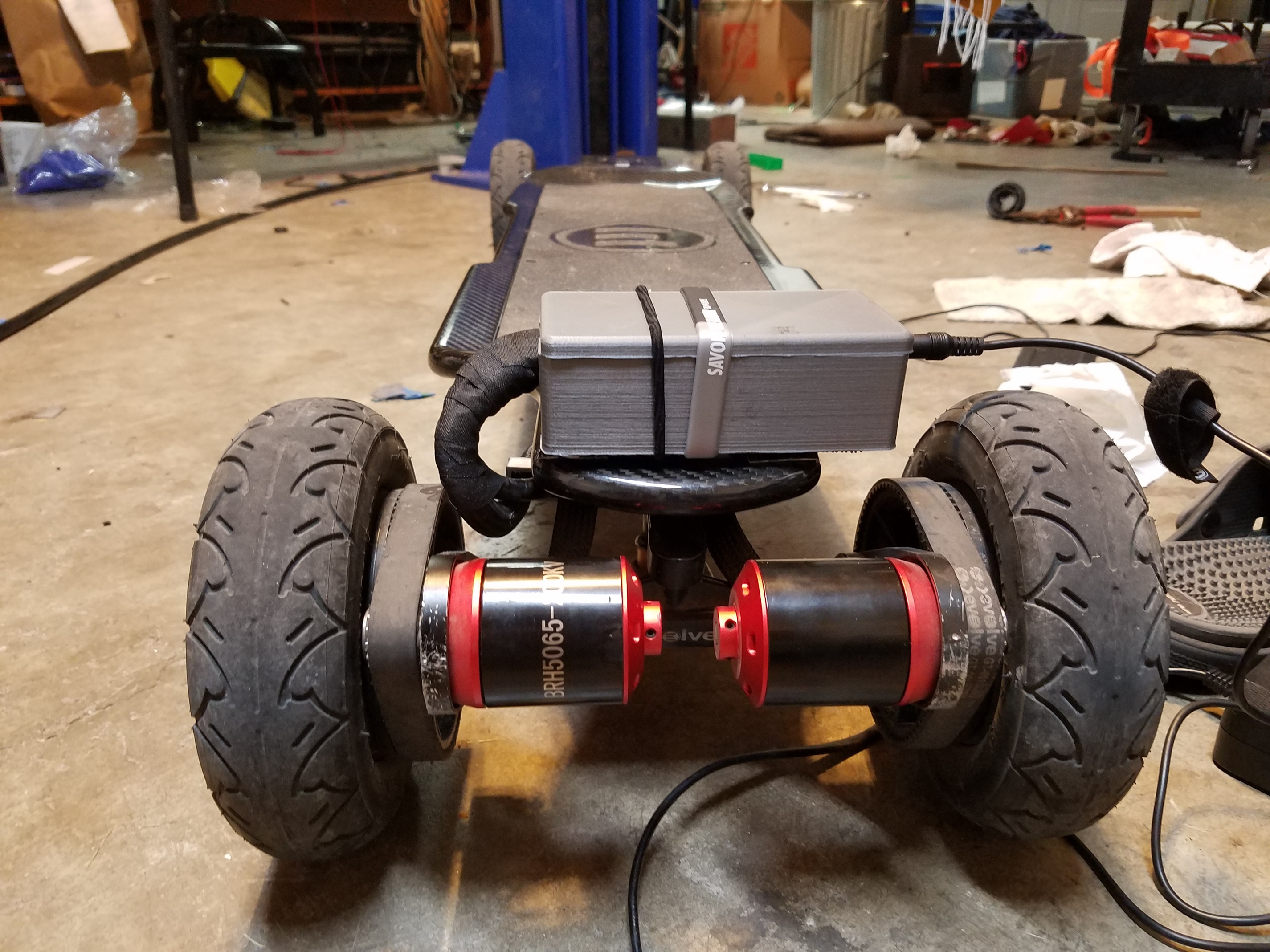
Next I opened up the evolve and took out the old junker battery:


Then It was time to inspect this bad boy(evolve bms), and trace down each and every BMS wire. It actually wasn’t too hard at all.
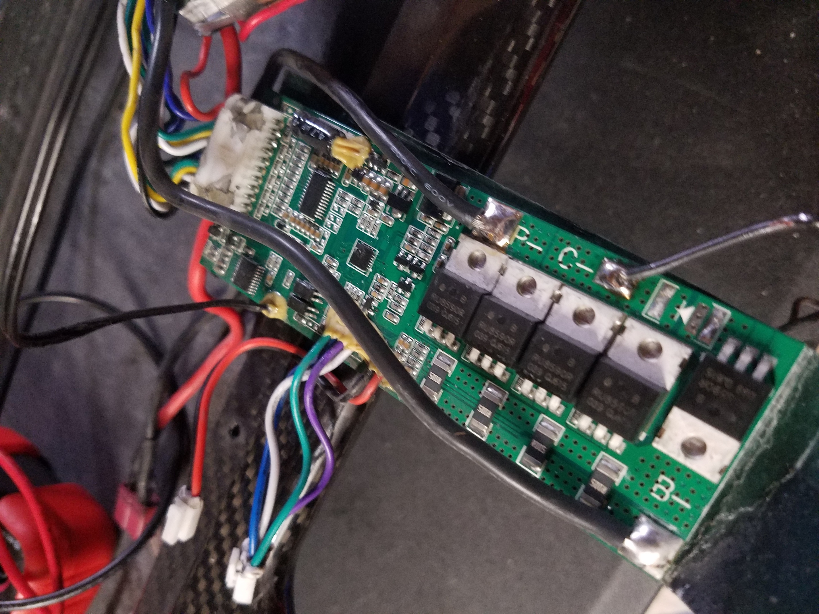

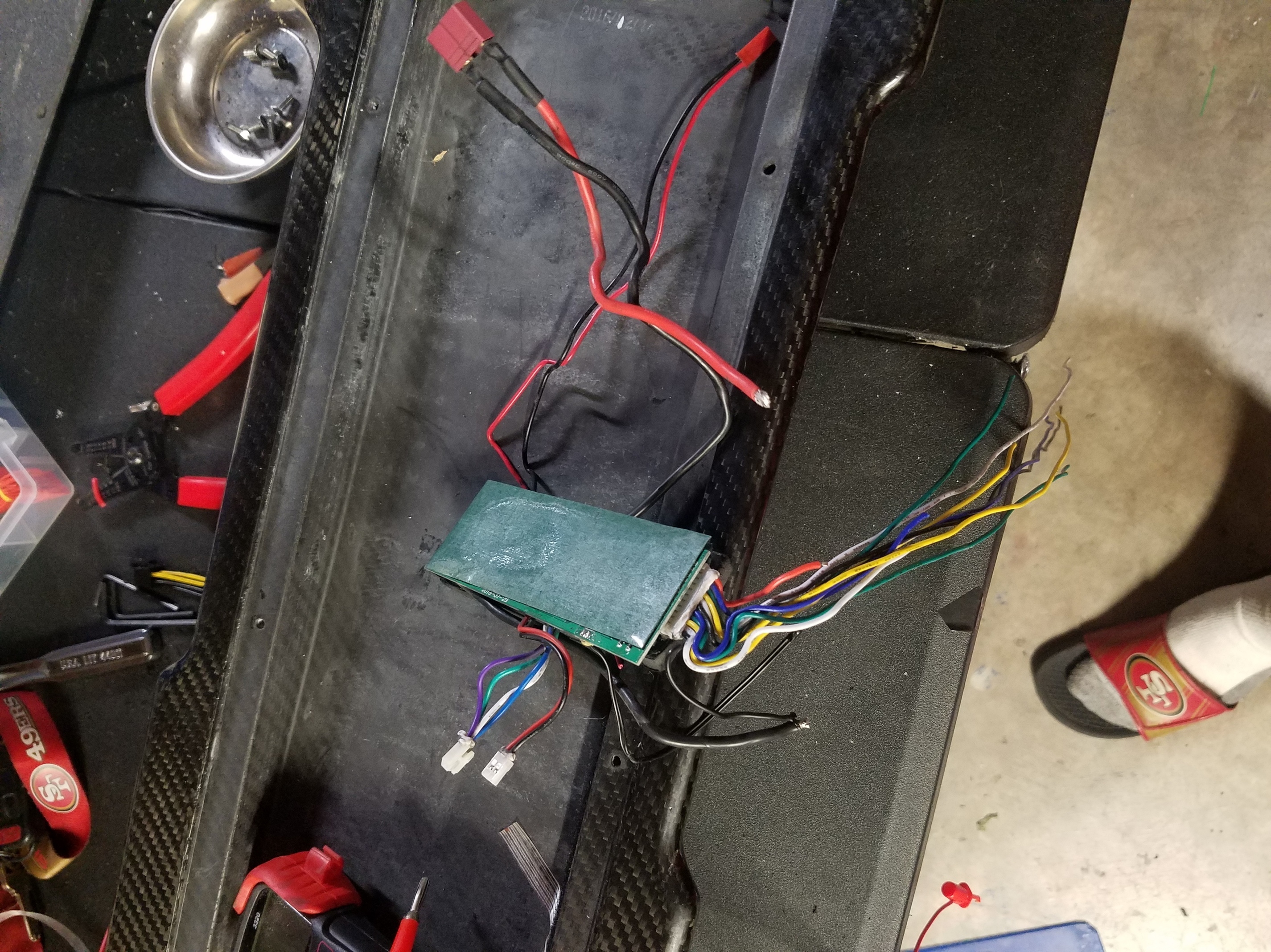
The balance lead closest to the RED wire(the blue one closest to the red wire on the balanace lead connector) is 1S, then just go down the line from there all the way up to 9s.
.
Test fitting the cells:
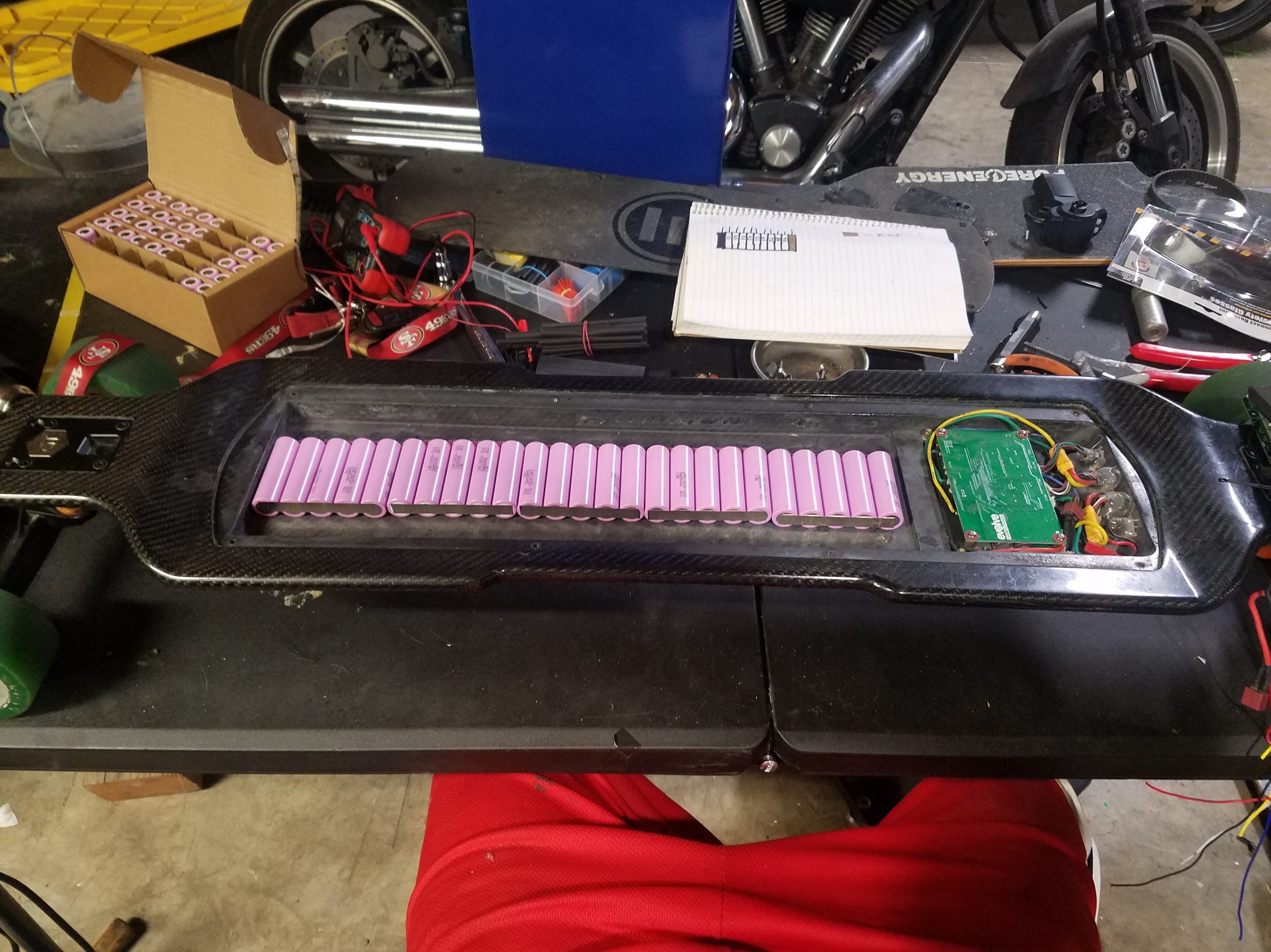


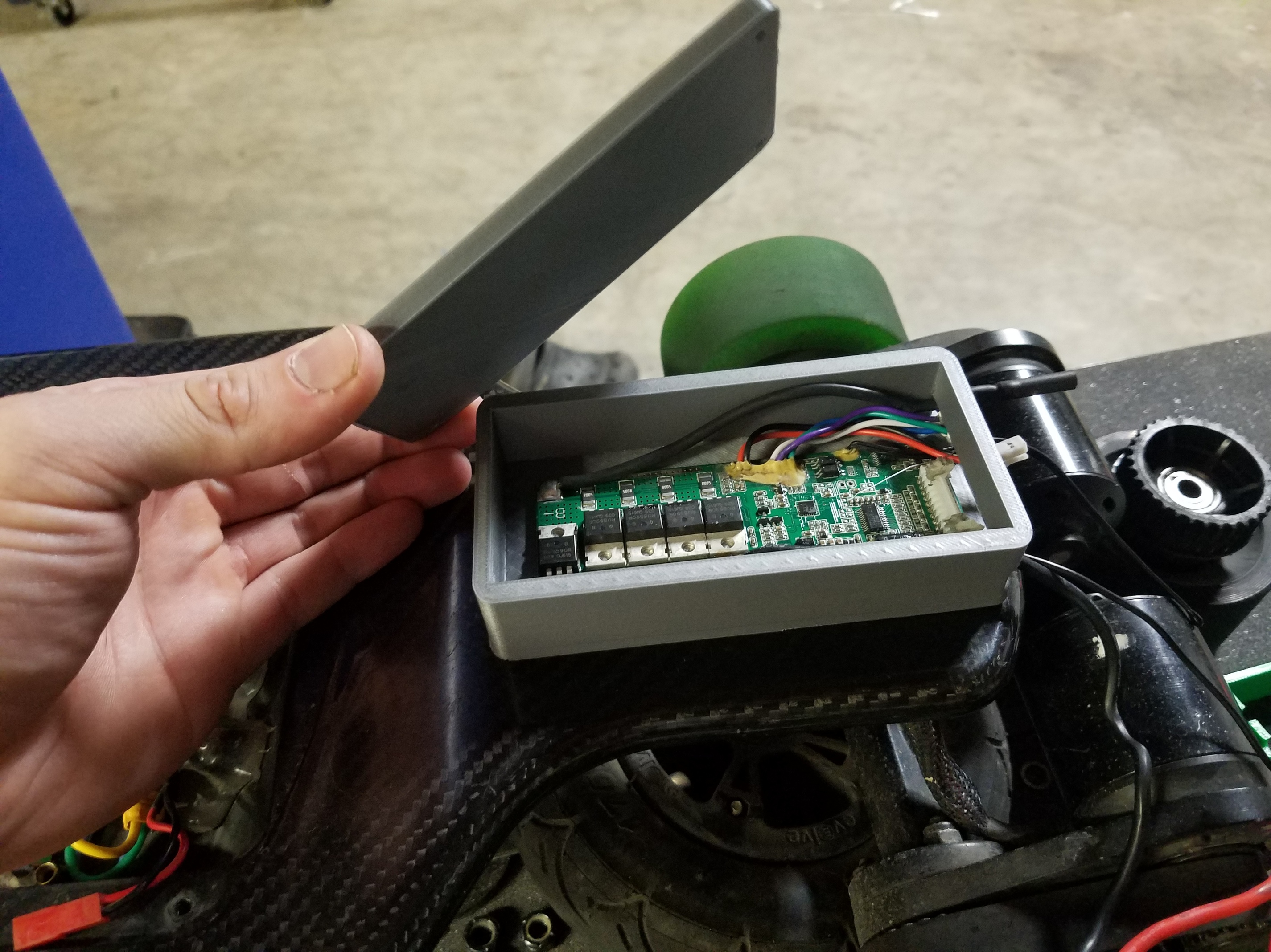
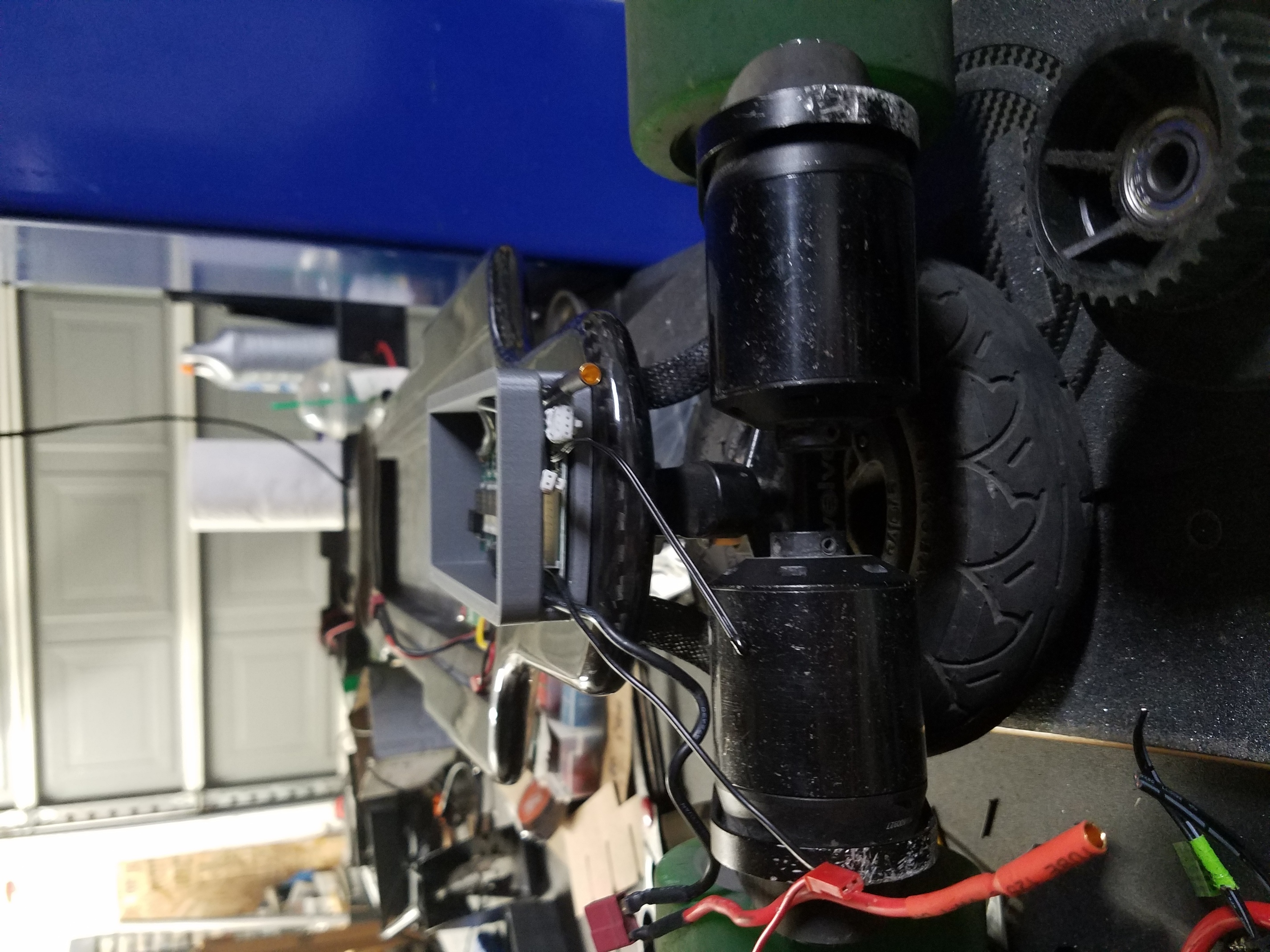
At this point, I found out that 50 cells and the evolve bms just wont fit very well in this compartment. I didn’t want to smash it all in there and risk damage. So I made the decision to relocate the Evolve BMS to the top of the rear truck area. I figured I never use that area on the drop through deck anyway. I even though about putting in an extra 10 cells there too… but I just feel like it will be too bulky. That led me to create this BMS case with my 3d printer. I still might make some revisions to this bms case, when I’m all done I’ll upload the files. Printr: printrbot simple metal with DIY heat bed installed. More on this later…


Time to start spot welding some cells! I made 10 packs of 5 parallel cells. My plan is to essentially make two 18v packs and connect them in series.


After spot welding it all together I decided I would carefully try to see if it would all fit into the compartment. This is where I ran into some issues. The first thing I want to talk about: BEWARE, THE DECK HAS CONTINUITY! I set down half the pack in there and smelled something burning. My pack was shorting… I quickly got it out of the deck, and only a small burn mark remains inside of the enclosure area, no serious damage.
At first, I thought that some of the nickel strip had shorted out something out on the positive end of some of the cells. I had some issues early on with some of the strips bending due to mis alignment and then shorting(which is why I will ALWAYS recommend using those cardboard protector ring caps[ill post a link]).
Long story short after some investigating I had a thought: “they make motor brushes out of carbon… maybe the deck combined with my non insulated pack caused it to short”. Grabbed my multi meter, and sure enough there is continuity in multiple places(not everywhere). So… anyway, for anyone doing this beware of that. I instantly thought of the board that lit on fire on the evolve forums. tldr: be carful.
Luckily, the extent of the damage was only about 3-4 cells due to the nickel strip acting like a fuse. I used my 10 extra cells to swap out any that were even near the short. Here’s the damage(looks worse than it really was):


After that turn of events , I got everything cleaned up and carried on. I double insulated EVERYTHING. I soldered in all my balance leads, and labeled them accordingly, connected the two in series at the back end. Then, It was time for a test run!:

ALL GOOD ![]() Then it was shrink wrap time(back ones are exposed because I had to make the series connection).
Then it was shrink wrap time(back ones are exposed because I had to make the series connection).

Then I added some duct tape for support.

AAAANDDDDDD after all the shrink wrap and tape: NO FIT ![]() . I’ll have to relocate the balacing wires to the middle and hopefully that’s all the clearance I need. It’s super close, but I dont want to force it.
. I’ll have to relocate the balacing wires to the middle and hopefully that’s all the clearance I need. It’s super close, but I dont want to force it.
that’s pretty much as far as i’ve gotten thus far. I except to finish some time in the next few days or so. I still have to:
Extend the battery switch, and UART cables to reach my new BMS location and clean up some of the wiring and such. If you’ve made it this far THANKS FOR READING. I’ll update this post as often as I can.


 <
<