So while I’m waiting for the PCBs for the FlexiBMS - 0.2 HW under work - Flexible configuration and charging BMS - ESK8 Electronics - Electric Skateboard Builders Forum | Learn How to Build your own E-board to get fabricated and shipped. I’m designing another tool that I need to upgrade in my arsenal, which is my battery tab welder.
If you’re wondering about my gripes and gubles with my old welder, refer to my 50 cell pack build over here: 10S5P Battery Pack build log. 50 pieces of Samsung 35E cells - ESK8 Electronics - Electric Skateboard Builders Forum | Learn How to Build your own E-board
Overall, the welder is a sub-performing mess, due to the heavy batteries and mess of wires and I’m not happy with it’s performance. So what do? Well first let’s look at what the professionals use in a more industrial settings. Video starts at the battery welder part.

So usually there are one of two types of welder power sources used. They either use a capacitor bank that they charge up to a certain voltage and then discharge it with a precision pulse or double pulse, which’ pulse lengths are configurable. Or they use a welding transformer to step-down wall AC voltage to lower a voltage, but higher current one.
In the video due to the manufacturer and model info being hidden by the tape on the welding machine, I can’t confirm the power type for that particular one.
Practical examples of both: Capacitive, front control knobs allow you to set the capacitor bank voltage, which is indicated as the stored energy in Ws (Watt-seconds) and two knobs to configure the lengths of the two pulses:
Welding transformer. Now, if you happen to check out the ebay link, you’ll find that this particular machine runs in the 3000+ dollar range + same goes for the capacitive ones and I’m not willing to put in something like that. https://www.ebay.co.uk/itm/Pneumatic-Pulse-Battery-Spot-Welder-Welding-Machine-18-Kva-3500-A-Ps300-B-/112415963445?hash=item1a2c837935
So DIY route to glory then? Ok, I’m familiar with capacitors and I can see many upsides if the welder is done right with them. I’m taking some concepts and ideas from this particular build Zero Emission Vehicles Australia ,but I’m looking in to make it a bit more refined, but still as simple and easy to assemble as possible (No soldering of any thick wires). And allow it’s integration into a CNC setup like in the video.
I’m going to build the welder out of 3 main blocks. Capacitor bank, electronic switch and microcontroller board. This way I can make it more modular and not having to risk total redesign of something didn’t work in single integrated package.
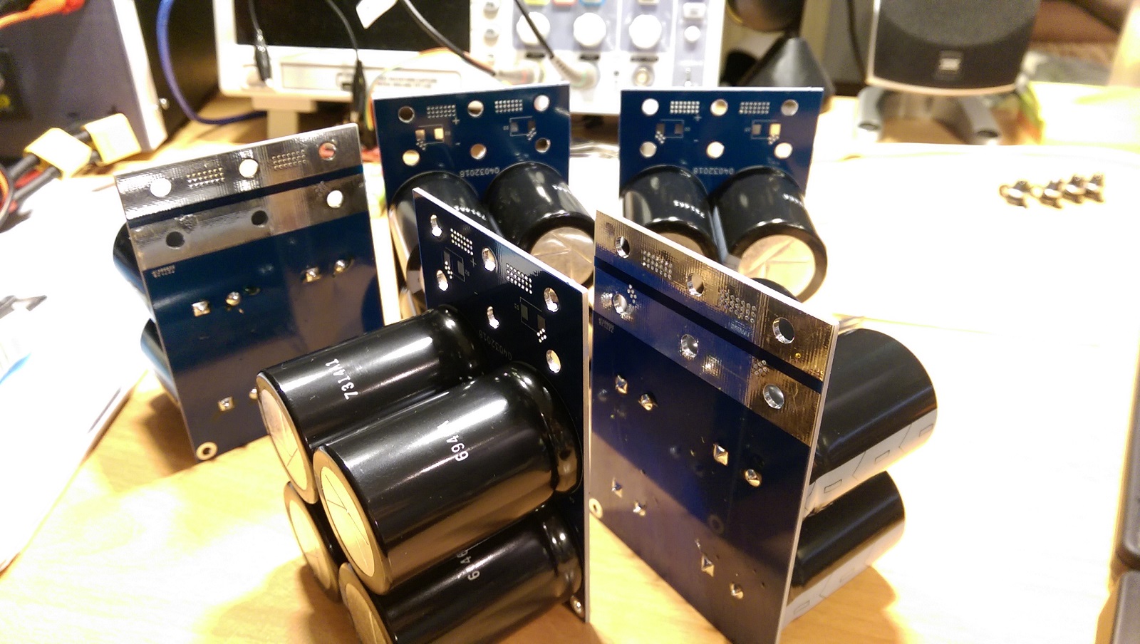
I currently have the capacitor bank and electronics switch boards modeled up with pictures below.
Capacitor bank board with integrated TVS diodes to protect from inductive voltage spikes, which can be a real issue with high currents and parasitic inductance in the cabling. Current capacitor choice https://www.digikey.fi/products/en?keywords=25USC47000MEFCSN35X50

Electronic switch board. Uses Intelligent Power and Sensing Technologies | onsemi beefy mosfets, with added TVS diode to protect from inductive voltage spikes.


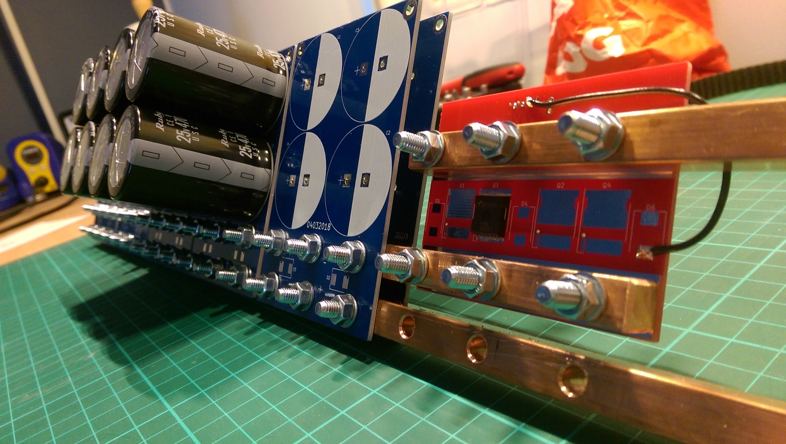
And here’s a quick and dirty blender render of the setup bolted together, without the microcontroller board.


With 20 Caps of the before-mentioned model, it would have the theoretical energy of ~290 Ws, which is pretty beefy amount of energy and adding more capacitor boards is quite easy with just longer busbars and double side mounted boards, which are just bolted to the busbar.
All-in-all I want to build this welder to get away from the chemical power sources, AKA batteries. I see them problematic with repeatability and performance over time degrading due to the chemical breakdown happening inside them.
Thoughts and discussion on this?