BIG TORQUE - Reliable board for the larger rider + DIY CNC Tab Welder

First thing to arrive was Samsung 30q cells.

IMG_20190403_224534

100 of these for 2x 12s4p packs plus a few spares to practice on (maybe a new battery for my fat-shark goggles)

In order to facilitate gluing these together squarely i knocked up a few quick jigs which held the cells together whilst gluing. After doing a few quick tests and some reading i decided to use hot glue rather than silicone. Also made sure to squeegee the glue well down in between the cells to maximise glued surface area. Found the end of a spoon handle worked well for this.

IMG_20190406_104130

After gluing i protected the positive terminals with these 4p fishpaper stickers(also from eu.nkon.nl)

IMG_20190406_112018

Finally a quick test fit on the board. All is looking good so far.

IMG_20190406_112647

6 Likes

Next fun toy to arrive was the spot welder. We decided to buy a DC style diy spot welder rather than an AC Chinese style one.

We went for the Malectrics “DIY Arduino Battery Spot Welder Kit V3.3” as i have seen quite a few people using these and having good success. we own lots of 4s miniquad battries so decided to go for the " Full Bundle for Lipo Battery". https://malectrics.eu/product/diy-arduino-battery-spot-welder-kit-v3-2-2-full-bundle-lipo-battery/

Arrived quickly from EU and was easy to assemble (once we managed to find the instructions).

IMG_20190412_213118

Powered it up from a small battery to test it but soon wanted to get some more power and test the welds.

This is where we hit a problem. It only runs off 3S lipo and all my miniquad batteries are 4S. Fortunately im a hoarder and i have a stash of damaged quad batteries (knew they would be useful for something). After some lipo surgery and removing damaged cells i managed to make 3x 1400mah 3s batteries. We were able to run these in parallel with another 2x 3s batteries that i had to make up a 3s 7000mah power supply for the welder.

IMG_20190412_213153

Initial test went well. According the the welder we were achieving pulses of around 600A. I do think we need to mount the probes in order to get consistent placement but other than that they seem sufficiently strong.

IMG_20190417_222549

5 Likes

Last post for today is about our @Kaly enclosures.

As i said previously we went for the kaly enclosures because i like the layout and like that all the mounting hardware is included. Kaly boards are awesome and i think i would of considered one instead of diy if i was in US. I also like the individual cell fusing and battery PCB’s that they offer as a kit.

We ordered a pair of enclosures from kaly.nyc 2 weeks ago from US to ship to UK. We also added 2 sets of the Cell Fuse PCB kits. Unfortunately on the new site there is not option to pay extra for expedited shipping or even tracking but we ordered anyway knowing that they would arrive . . . at some point.

Finally after 2 weeks of waiting patiently i got my delivery notification today. Super stoked when i received the package.

THE GOOD

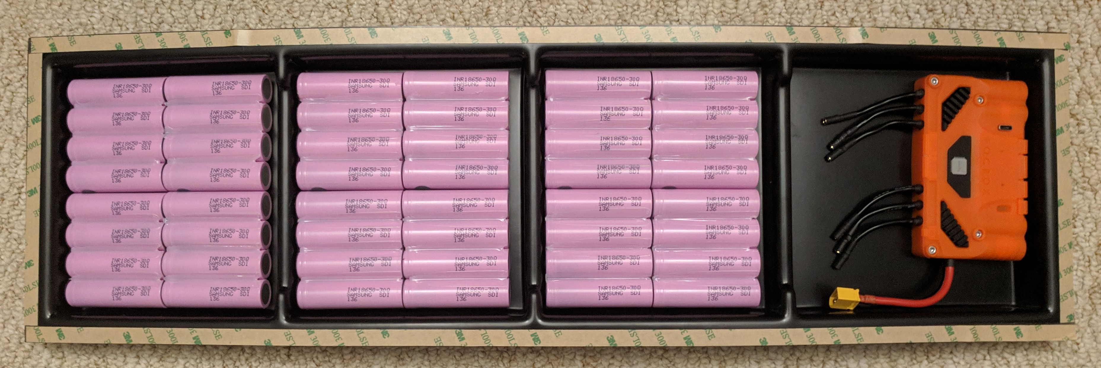
Enclosure looks good. Finish is nice. Material is thicker than I expected (which is a good thing) yet it still flexes easily.

IMG_20190417_225239 IMG_20190417_225244 IMG_20190417_225258

Everything fits well and there is enough space for vibration isolation around cells and electronics.

IMG_20190417_225728

THE BAD

Firstly the enclosure is going to need modification to fit the carver deck.

IMG_20190417_225419 IMG_20190417_225426

The enclosure is described as being compatible with the Urban Carver but dont think it will be without modification. The corners will need to be substantially cut in order to fit on the deck without overhang or causing wheel bite. This concerns me as cutting this much from the corners will affect the amount of sealing around the corners and may affect the waterproofing of the enclosure.

Also it looks like the enclosure was cut from its panel with a CNC. It surprises me that the corners are not cut to fit on the cnc whilst the profile is being routed. It would lead to a much neater job than any user will do by hand.

Second minor issue is that my battery cell pcb’s are white, not back as shown on the website. Whilst This is not a deal breaker it is a shame that what you see is not what you get.

IMG_20190417_231755

THE BITS THAT I DONT HAVE

My final and fairly major problem is that there is a large amount of my order missing.

Firstly the order only includes ONE enclosure and ONE cell fuse kit instead if the TWO on my order confirmation.

Secondly the one enclosure that i did receive is missing a large number of the parts the website says it comes with. I am missing all the screws, all the threaded inserts and all the mounting plates.

Additionally the CELL fuse kit that i received it is also missing the heat shrink that is supposed to be included with it.

What does this all mean??

Unfortunately without the cell fuse PCB’s for both builds there is not much that we can do to continue. There is not much point in trying to get one board built up as we don’t have all the mounting hardware to get it finished and it means setting up the battery welder twice rather than doing all the cells in one go.

I guess there not much we can do now except wait to hear back from @Kaly and hope that he can get this sorted out. Just sucks that we will likely have to wait another 2 weeks for things to ship from over seas again.

3 Likes

If something is worth doing then its worth overdoing right?

build%20v3-2 build%20v3-3 IMG_20190424_233849

10 Likes

where did you pick up the batteries?

cells are from here :

TAB WELDER PROGRESS.

So lots of people are asking “why bother” and to be honest the short answer is BECAUSE I CAN.

The long answer is that i need to build 2 x 12s4p packs soon and potentially another 2x 14s4p packs for some e-bike friends in the near future. Thats 52x 4p packs or 208 cells each with 3 welds on both ends.

THAT IS 1248 WELDS .

1248 times I have to hold those awkward probes int he right place and concentrate.

Sounds tedious to me so i decided to have a go at creating something to automate the process (at least partially).

This is where im at:

IMG_20190425_223247

The idea here was to make something that can make my welds precise and repeatable but requires the minimal amount of effort to build.

The current design includes 2 stepper motor driven linear stages. The X axis can position cells under the welding head. The Y axis moves the weld probles away from the cells, This axis is also spring loaded so that once contact is made the lead screw can be used to apply consistent pressure to the weld head.

IMG_20190425_223138

I was considering adding a another axis to allow the weld head to move up and down however it i think this would vastly increase the complexity and im only likely to need 3 positions in the z axis so i might be able to achieve this by placing spacers under the battery pack.

IMG_20190425_223315

The linear stages are made from cheep parts from Banggood which i acquired for another project but never got round to using. The bearings seem to be ok but everything else is made of chinesium. It is designed such that dimensional tolerances (or lack thereof) should not be critical to operation. Im kind of glad i never tried to build a real CNC with these parts.

IMG_20190425_223305

I still need to design a way of holding the cells and welding probes accurately in place but that is a challenge for another night . . . probably tomorrow night as im desperately trying to get it done before the rest of the kaly PCB kits and enclosures arrive.

18 Likes

Still waiting for my replacement kaly parts. seems like the first lot went through fine but the second shipment got stuck in customs :frowning: im £35 lighter but at least they should be here monday :slight_smile:

In other news we have been making good progress on the tab welder. Yesterday we finished mounting the lead screws and wiring up the stepper motors to a controller.

Imgur

you can see it running a quick 2 axis weld pattern doing 1 weld for each cell. The spring system in the top axis allows for repeatable pressure on he weld tips during welds.

Imgur

Additionally we decided to go all the way and add a third axis to the weld head to allow for doing all 3 welds per cell without having to adjust things. this is what the 2 upward facing steppers are for. these will eventually have small lead screws and give the weld head around 12mm of z travel which should be enough for spacing the welds.

IMG_20190427_232439

I have also designed a more accurate holder for the weld tips and cells. the weld tip holder is made of 2 parts that clamp the tips in place and bolts to the z axis. Cell holder also bolts directly to the x axis.

IMG_20190427_232505

The cell PCB (with pre soldered nickel strips) fits snugly into the cell holder.

IMG_20190427_232545

The cells then slide into pace above this. The printed part is pre-tensioned so that cells are held accurately. Tabs will then be bent up over the front ready for welding.

IMG_20190427_232714

Despite basically making it up as i go along im very happy with how this is progressing so far.

13 Likes

Woao, very very good job & step by step progress report.

Brilliant! I did my 12s6p with the same welder, this method will ensure no burnt fingertips!

Finished the hardware tonight tonight.

IMG_20190428_224819

IMG_20190428_224619

IMG_20190428_224633

Just got some electronics and software tweaks to make before I can test it out . . . Maybe tomorrow if I get time :smile:

17 Likes

That’s cool stuff, I’m curious how much it costs in parts of you happen to know it care to guess.

1 Like

I built this mostly from stuff laying or purchased for previous projects around but these are the main parts :

2 x Cheep linear axis kits - £17.85 each https://www.banggood.com/15pcs-Optical-Axis-Guide-Bearing-Housings-Aluminum-Rail-Shaft-Support-Screws-Set-CNC-Parts-p-1276180.html?rmmds=detail-left-hotproducts__3&cur_warehouse=CN

Arduino with cnc shield & stepper drives - £7.87 https://www.banggood.com/CNC-Shield-UNO-R3-Board-4xA4988-Driver-Kit-With-Heatsink-For-Arduino-Engraver-3D-Printer-p-1082323.html?rmmds=search&cur_warehouse=CN

2x small nema17 (Zaxis) and 2xlarger nema17 (X&Yaxis) stepper motors. Seems to cost ~£10 each but i had some laying around from 3d printer projects.

All acrylic was scraps that i have collected. only other parts are a few printed parts + screws and mounting hardware.

All in all if you had to buy everything i would guess around £100 for all the hardware + some acrylic. I used it cause i had it but i guess wood would probably do just as good a job if that is what you can get hold of.

3 Likes

For different cell sizes would you just manually adjust the Z mount

Presumably a different set of code is required

Variables? Cell type, parallel group size, No. of welds, Weld pattern? Something like that

Cool beans my man

I could see this being used with the Boss welder using the foot pedal connector

I guess the cell holder part could be reprinted for different size cells which would mean that z axis would not need to be adjusted much. longer x axis might be needed for more than 4P groups.

At the moment the cell count, welds per cell and distances between welds are all adjustable for fine tuning.

Im currently using the welder foot pedal just to start the weld sequence but i may change it to do one cell at a time depending on how much monitoring it requires when running.

1 Like

If you rotate the head 90 degrees so it’s vertical, doing 3 side by side welds per cell will give you the 2x3 contact area without having to space it up every time, just set it down for the 12 welds

3 Likes

Thanks it’s sweet but I use the outer holes, any chance of an accomodation for that or the fusion file in order to tweak?

image

Here’s what happens if you pull those holes through the riser from a sketch of the hole placement from a HolyPro

Im definetley interested in getting or making one of these!

Really nice work, could you help me out a bit with the electrical part of it?

Im assuming it wouldn’t be complicated to make it possible to weld 3-6p pack?

@Kaly enclosures arrived today for both boards along with all the missing parts plus a few extras :wink: so I don’t feel too bad about having to pay some extra customs charges.

IMG_20190429_231318

IMG_20190429_231339

Both enclosures look great and my friend and I are super excited to get building.

IMG_20190429_232041

I was a bit worried that the LLT Bluetooth BMS and Unity might not fit side by side but it looks like there is space and maybe even a little room to spare.

IMG_20190429_232116

@ZachTetra that is a great idea . . . About a day to late. Unfortunately I already finished the z axis but your way makes much more sense.

@banjaxxed I’m sure it could be modified to fit all the cables between those holes. I’m away from my pc at the moment but Im happy to share the fusion files with you when I’m back at my pc in a few days if you can wait.

@Acido electronics has been quite easy. If your using that CNC shield I linked then you basically plug the steppers in and your good to go. I can share my code if needed but it’s not that pretty. Doing 6p packs should be fine if you add a longer X axis travel.

That said I haven’t actually welded any cells myself yet so maybe we see if it works out first :slight_smile:

6 Likes

thanks! that would be super-de-dooper