Hey guys,
For the past 2 and a half years, I have been working on an interactive lighting system for diy electric longboards.
It all started when I was in college and decided to add head, tail, and RGB side lights to my longboard. I wanted lights that would turn off when I picked the board up and turn on when I dropped it back down, so I created a controller that would take IMU measurements and turn them on and off based on the board’s orientation. Shortly after finishing that project, I started a project based course in which we got to build any embedded systems project we wanted. My team decided that we would build off of my hobby project and make an electric longboard with interactive lighting, a HUD, and various safety systems built in. When that project was completed, I was allowed to keep all of the parts we used since I was the only longboarder in the group  Since I had most of the expensive parts already, I decided to make my own proper electric longboard. When looking into motor controllers, I was immediately sold on the VESC because of it being open source and the awesome, dedicated community it had. When looking further into the VESC I realized that I could integrate my lighting controller project with it to gather motor data and use that to further the lighting effects that I had already created. That’s when I made the first version of what I am now calling the TelTail Lighting System.
My goal when I started this project was to create a lighting controller that was tailored to my system only and didn’t consider making it flexible to meet the needs of other community members. However, as the project matured, I kept adding features that accomplished just that and finally decided that I would go for it.
The first version I made was designed to plug directly into the original VESC.

That worked well for my purposes, but by the time I decided I would share the design with the community, the VESC hardware had changed. So I updated the design to use the same 2mm JST headers used on the VESC for all external connections. This allows the lighting controller to be a plug and play module and provides vibration resistant connections. I also removed the SD card slot and added a 12v buck circuit to the design. I removed the SD card slot because I began developing an android app and was able to log data through that instead.

After doing some testing with the v2 design, I found the 12v buck circuit I was using to be unreliable. Because of this, I updated the converter to a more dependable one. The new converter is rated for 30W @ 12v, which is just enough to supply power to the head, tail, and side lights. I also removed all unused connector pins to make room for 3 more ports; a 12v output, an auxiliary switched 12v output, and an input for the button channel of a PPM remote.

To give people options, I also created a second variant of the design that replaces the 12v buck converter with a spring loaded terminal block. This variant is cheaper and allows the user to supply power to the control module using a more powerful DC to DC converter like the one here. The connector is rated for 10A so you can even supply upwards of 60W withought issue.

The auxiliary output was added to v3 of the control module to allow the user to control a 12v motorcycle horn like the one found here, however, the FET on the TelTail Lights (TTL) control module will get fried if the horn is driven directly from this output. To solve this issue, I designed the High Power Control Module (HPCM). This expansion module allows the aux output to control a FET that is capable of driving the horn without burning up.

When I started developing the TTL control module, I could not find a 12v headlight or tail light that suited my needs so I decided to design my own. For the headlight I wanted something that mounted under my board, was bright enough to light my way on a road or path, and was not glaring in the eyes of people I passed by. To do this, I designed a PCB with 2 bright white LEDs, designed a 3D printable housing that mounts to my trucks like an 1/8" riser, and used oval lenses that cast the light in a wide narrow beam low to the ground.

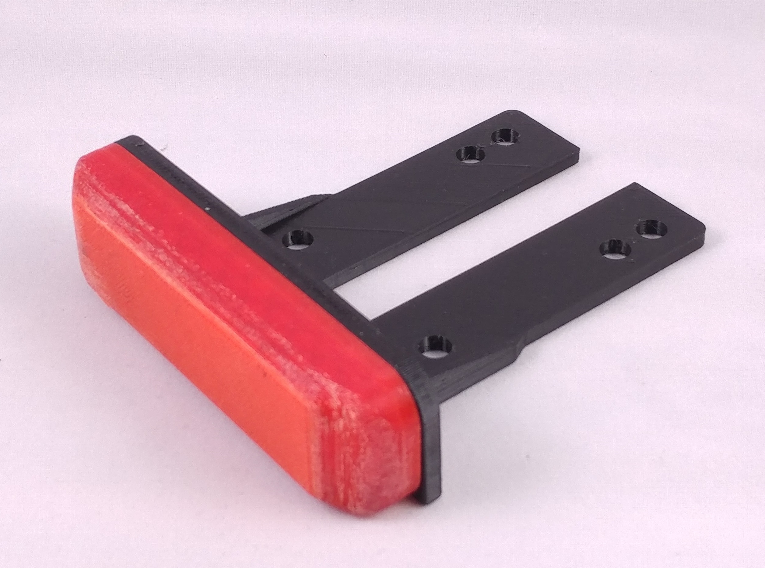
For the tail light, I wanted something that created a bright red light but did not cast that light into the eyes of people behind me. To do this, I designed a PCB with 3 bright red LEDs and a housing that mounts to my trucks like an 1/8" riser and diffuses the light to create a glowing bar that lights up the ground around it.
I have a couple videos of the lights and their effects on my instagram page, here’s the link if you want to check them out: https://www.instagram.com/mattsauve/
Since I have seen many people already use lights like Shredlights, flashlights, or floodlights, I wanted to provide a way to use the TTL control module to control those lights as well. To do this I designed the Low Power Control Module (LPCM). This module allows you to control the power switch of a light with a built in battery using one of the switched outputs of the TTL control module.
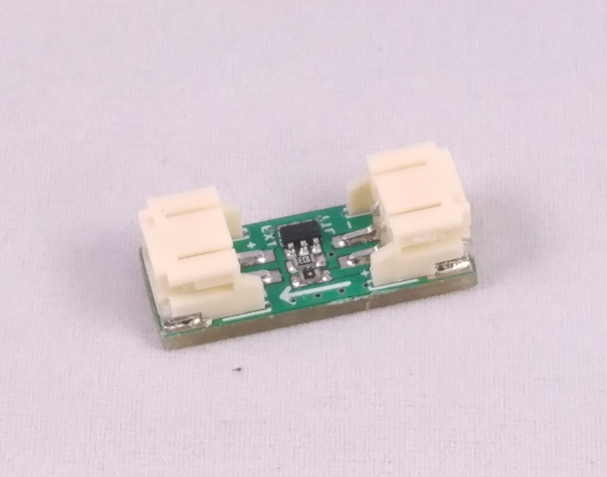
The latest module that I designed is the Analog to Digital (A2D) Module. I made this module because I want to be able to control digitally addressable RGB LED strips with the side light ports of the control module. Though I have tested that the functionality of the module works, I haven’t developed the code to actually utilize it yet. Once I make all of the firware and app code for this project opensource, I hope that people in the community will help write this portion.

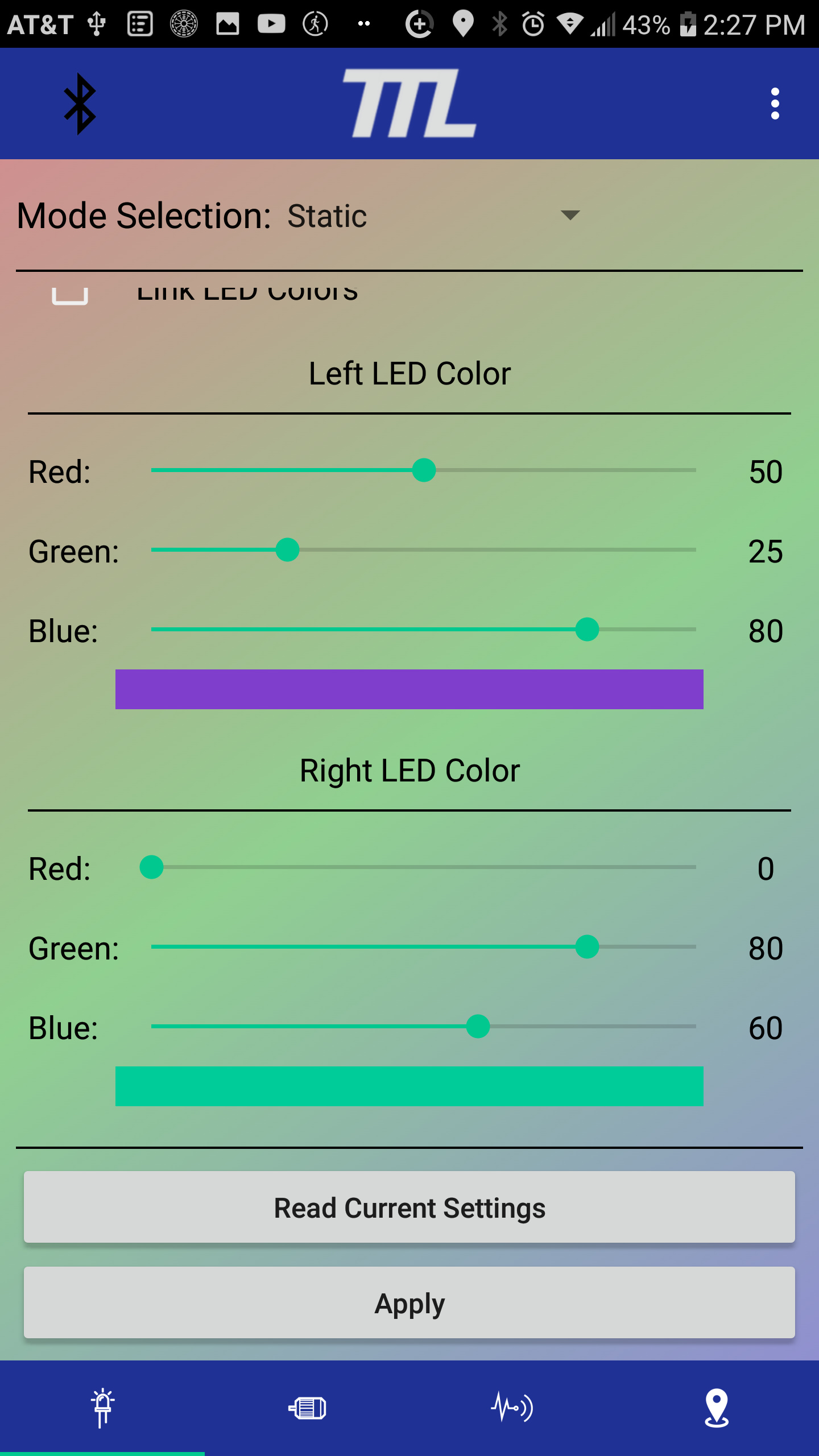
As mentioned above, I’ve began developing an app for the TTL System. The app has four main functions. The first is used to configure all of the settings of the TTL control module. The settings include: LED mode characteristics, module orientation, and how the eboard remote controls the lights.
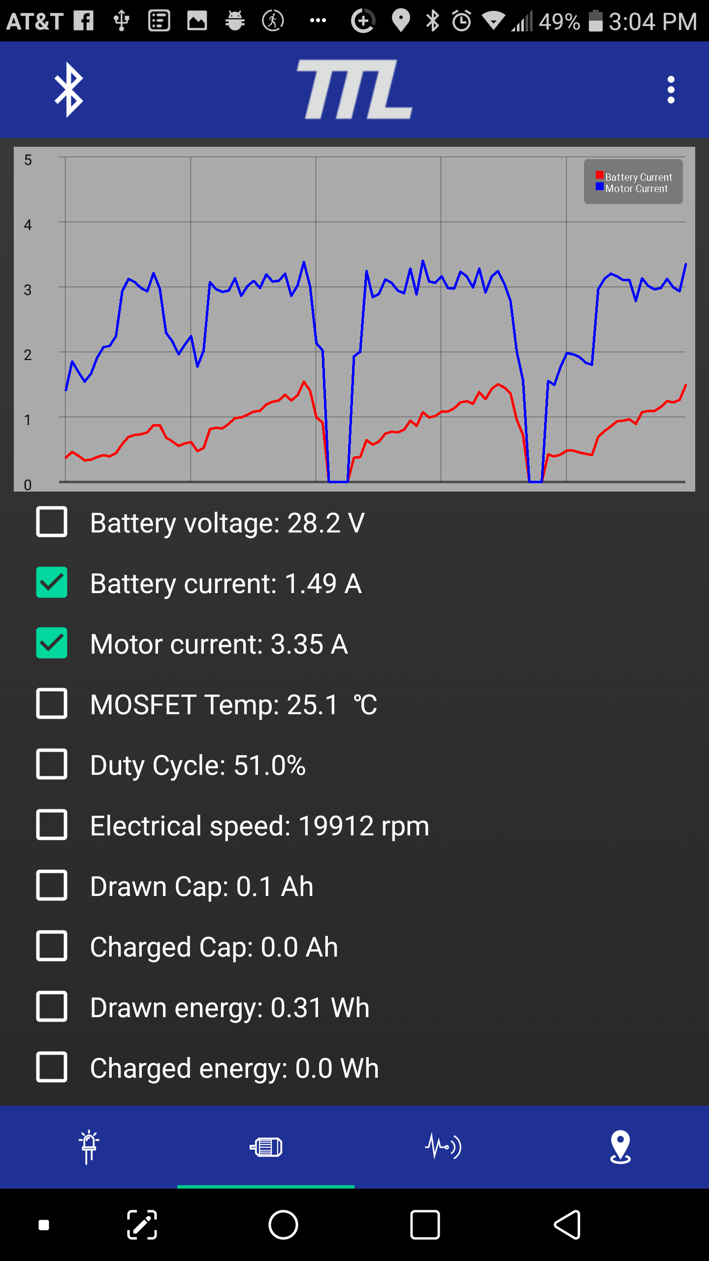
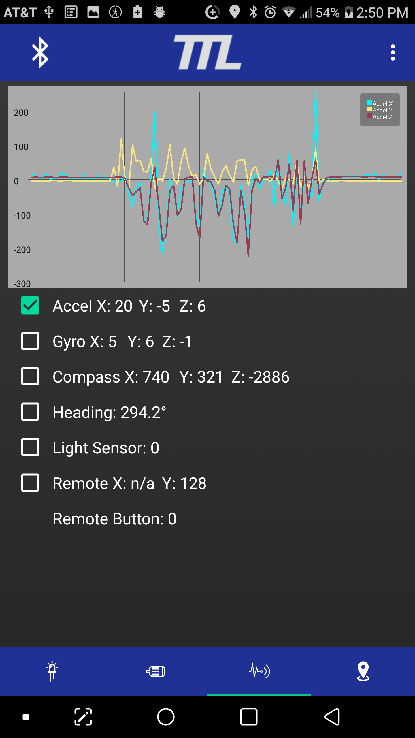
The second function of the app is to read out live data from the control module. There are 2 screens where live data can be viewed: the motor data screen and the sensor data screen. The motor data screen has a graph at the top that displays whatever information the user selects from below. Below the graph is a list of all the data read from the connected VESC based ESC with checkboxes next to them to select which item are displayed in the graph.
Like the motor data screen, the sensor data screen has a scrolling graph at the top that displays whatever readings you want. The data available is all of the IMU measurements, the calculated board heading, the light sensor reading, and the remote joystick and button states.
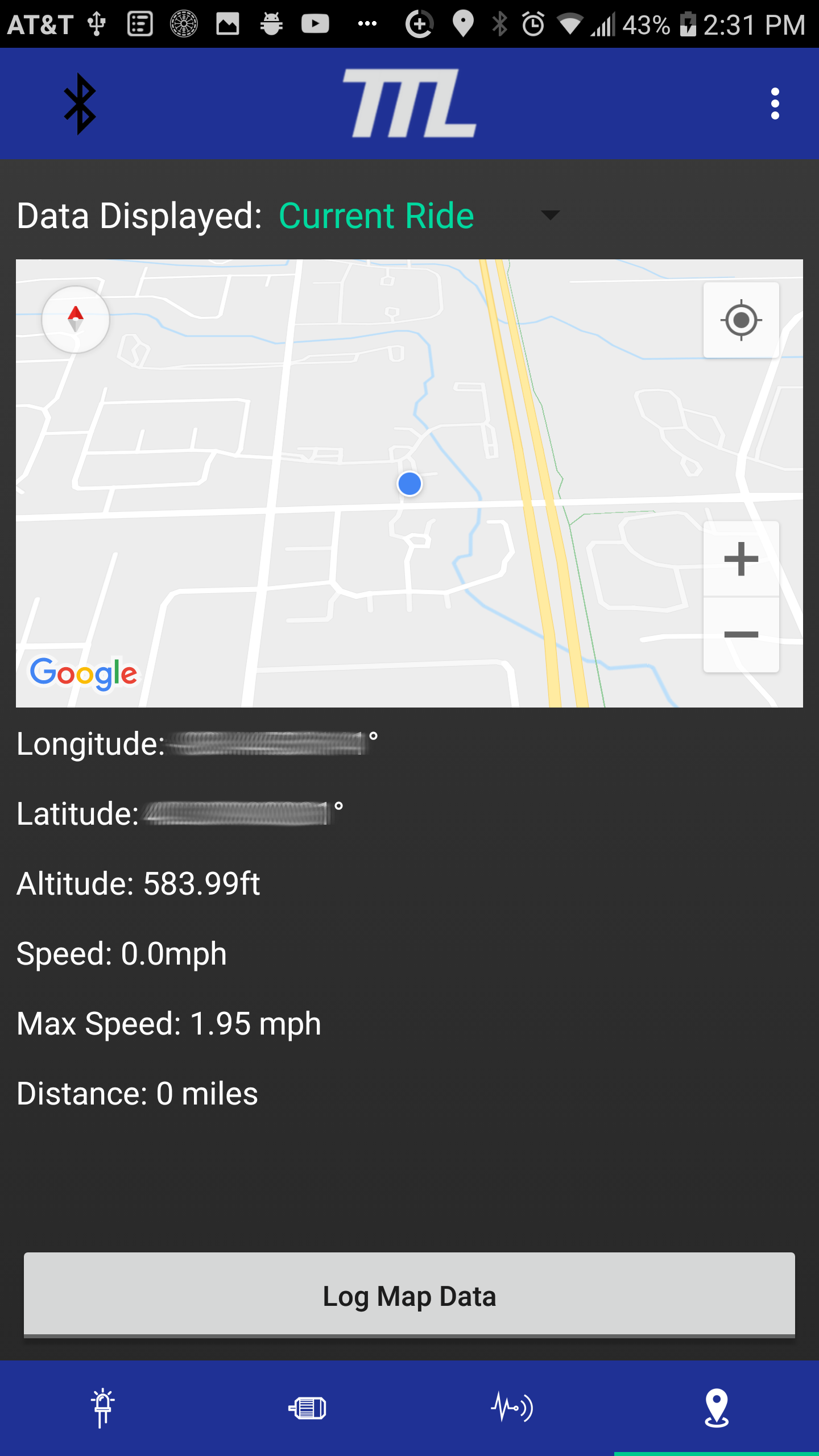
The third function of the app is to track the users path during a given ride and provide stats from that ride. On the map screen, the users rider path is displayed on the map at the top. Stats from the displayed ride are shown below the map. The stats include current longitude/latitude/altitude, currect speed, max speed, and distance travelled.
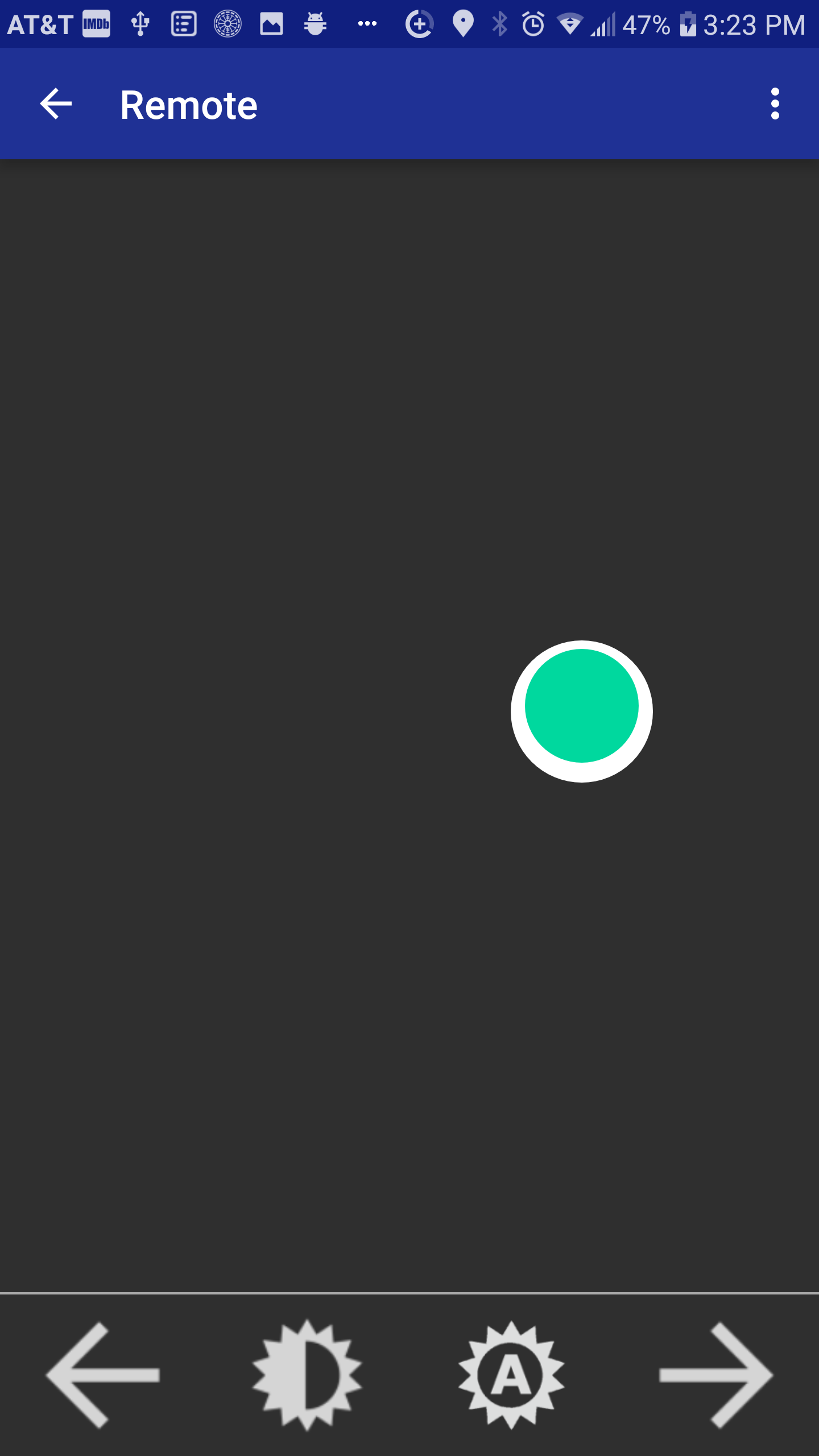
The fourth function of the app is to provide the user with a backup remote in case their primary remote dies or will not connect. The remote screen uses a relative joystick interface to control the throttle of the VESC based ESC. Wherever the user first places their finger will be the center of the joystick. If they move their finger up, it will increase the throttle. If the they move their finger down, the ESC will start braking.
I believe I am finally at the point where I can start selling the various modules that make up the TelTail Lights Project. I have created a website both as a project documentation location and a webstore for purchasing the boards that I’ve designed. I do not have anything in stock yet, though, because I wanted to gage everyone’s interest on this forum before having boards assembled. Please take a look at the links below to read more about the project, browse the items I want to sell, and download related files. Please keep in mind the prices in the store are all estimates at the moment. They will be updated once I gage interest and order assembled modules.
TLDR: System Overview (for more detailed info visit the documetation page of my site)
TTL Control Module Features
- 9 switched 12v DC outputs
- Head light
- Tail light
- Side RGB lights (6 total outputs)
- Aux output (designed to control a horn)
- 2A max each
- VESC communication (currently I2C, planned to change to UART)
- PPM button input
- Nunchuck port (a pass through of the VESC comms)
- Direct 12v DC output (for use with HPCM or other external devices)
- Light Sensor Input (to be implemented in code)
- BLE to connect to Android app
- Two Types
Self Powered (SP)
- Input Voltage: 20 – 50v
- Max Power Output: 30W (includes control logic)
- Power Connector: Male XT30
Externally Powered (EP)
- Input Voltage: 12v @ 10A max
- Max Power Output: Determined by DC converter used
- Power Connector: 16-24 AWG Screwless Terminal Block
Low Power Control Module Features (LPCM)
- Plugs into a switched output of the TTL Control Module
- Used to control battery powered lights
- Flash lights
- Flood lights
- Shred Lights (not yet tested)
- Controlled Voltage: 30v max
- Controlled Current: 3A max
High Power Control Module Features (HPCM)
- Plugs into a switched output of the TTL Control Module
- Used to control horns or high current devices
- Flood lights
- Horns
- Controlled Voltage: 60v max
- Controlled Current: 30A max
- Flyback diode included for horns (deconfigurable through PCB jumper)
Analog to Digial (A2D) Module Features
- Connects to a side light port of the TTL Control Module
- Designed to control digitally addressable LED strips
- Not yet implemented in the code
Android App Features
- Configure the lighting effects of the TTL system
- Sensored control can be turn on/off (turns lights off when the board is picked up)
- Light control can be turned on/off (not yet implemented)
- 9 modes for side RGB lights
- Static - Set each side light to a solid color you choose
- Color Cycling - Cycles through all colors at the rate and brightness you choose
- Compass Cycle - Controls the color based on the orientation of the eboard
- Throttle Based - Control the color based on the throttle position
- RPM Based - Controls the brightness based on RPM and the color cycles
- RPM + Throttle - Controls the brightness based on RPM and color based on throttle
- X Accel Based - Controls the brightness based on the x-axis accel reading
- Y Accel Based - Contols the color based on the y-axis accel reading
- Custom - choose for the various brightness and color bases to create your own effect
- View live data from connected VESC in text and on a scrolling graph
- View live data from the on-board IMU in text and on a scrolling graph
- View ride path and stats
- Control the motor’s throttle with virtual remote (meant as a backup remote)
- Get notified of fault codes issued by the VESC
- Log data gathered from the VESC, IMU, and/or GPS
- Configure how your remote controls the TTL system
- PPM and Nunchuck supported (UART remotes are planned to be added)
- Enable or disable turn signals (currently only working with Nunchuck)
- Customize the output type of the aux output
- Toggled
- Momentary
- Timed
- Pattern (not yet implemented)
- Customize what button presses perform specific actions
- Actions:
- Aux Control
- Toggle All LEDs
- Toggle Headlights
- Toggle Side Lights
- LED Mode Up
- LED Mode Down
- Button press types:
- Single Tap
- Double Tap
- Triple Tap
- Hold > 0.5s
- Actions:
- Calibrate the IMU
- Set the oriantation of the TTL Control Module
- Allows you to place the control module however you like in your build
Since this project has been my hobby project for a long time now, I have decided I have taken it as far as I want on my own, and I will be making it open sorce. That way anyone interested can help further the developement and new features can be rolled-out regulaly. I have posted the schematics and files required to assemble all of the boards to the downloads page of my website (link below). I have also created git repos for both the firmware and and the android app (links below). The only thing I will not be releasing as open source is the PCB designs. I have put countless hours of work into the PCB designs alone so I will be selling them on my site but not releasing the designs.
The app can be found on the Google Play Store HERE
Please visit my site to learn more about this project
- Documentation: https://solidcircuits.net/documentation/
- Downloads: https://solidcircuits.net/downloads/
- Store: https://solidcircuits.net/shop/
The code for the TTL control module firmware can be found HERE
The code for the Android app can be found HERE
I have pictures and videos of my project posted on my instagram page, here’s the link if you want to check them out: https://www.instagram.com/mattsauve/