Well let me start off by saying I’ve been lurking around here for a little while gathering information and ow I believe it’s time to contribute.
First a little background. I have a Master’s degree in Mechanical Engineering so it would be a fair statement to say I’m a bit nerdy. I’ve always been interested in building pretty much anything and spend the majority of my spare time in my wood shop making furniture. A few months ago I was introduced to electric skateboards by Casey Neistat and the Boosted Board. While I found the idea to be a novel one I found the board to be lacking. So after a few short minutes of googling I found that it wouldn’t be very hard to build my own to the way I wanted it.
Now there seems to be two thoughts to this process, build from scratch and assemble from parts. With my first born daughter still an infant I have more money than time so I chose the latter approach while fabricating what I could.
To start off here is my BOM with associated prices and comments for those that are interested.
Deck:
Loaded Truncated Tesseract $230
Trucks – Bears – wheels - risers: Callibur 2’s $54 Reds bone swiss $50 Orangatang Kegels 83a $60 Luxe 0.5 inch $4
Motor & mount: Alien 6355 HEV 190 kv x2 $73 ea Alien drive longboard diy 63mm kit x2 $145 ea
Electronics: Nyko Kama remote $15 DIY Electric skateboard VESC x2 $90 Parallel XT90 connector $9 CAN bus connector $7
Battery: Battery Bro Samsung 25R5 x50 $3.68 ea Dxsoul diy 4 slot 18650 battery holder x10 $32 Mean Well HLG-150H-42A Power supply $62
MISC: Wire, nuts, screws, ect. $50
Needless to say this project coming in at a total of $1373 was way more than my expectations in the beginning. But everything always costs more and takes longer than one would think, and I still came in under the price of a Boosted Board.
A few comments on why I chose certain items, to start off with the deck was for the simple reason that it is a tried and true deck that is compact and can handle speed. I went with Alien’s mounting kits because of all the others I looked at these appeared to be the better engineered, with minimal stress concentrators and well machined. I went with DIY’s VESCs because after scouring the forum they had the least complaints for the best price. Battery Bro was able to get me a decent price for a bulk buy of 50 cells, however I will say that shipping was a nightmare. It took well over a month to get the cells despite the fact that I paid extra to have 3-5 day air shipping and when I received them I was missing some additional items I had ordered, so it took another 2 weeks for them to fix it. I will say they refunded me for the items that were missing in the first package but it was still a disaster and I don’t think I would use them again. The battery charger I chose is not actually a charger, it’s an LED power supply. However it has a customizable output voltage from 37 to 47 volts and a max amperage setting up to 150 watts total output. So I set the voltage to 41.5v and 3.6A, I don’t use a BMS for reasons that WhitePony has outlined and the charger works quite well. It won’t charge the cells to fast due to the max amperage setting and as battery voltage approaches supply the current draw tappers off to zero.
But enough words let’s get to some pictures.
First up are the Alien parts, and while the quality is good I found the finish to be a little lacking, there were a number of burs on the Kegel adapters that had to be filed for proper fit.

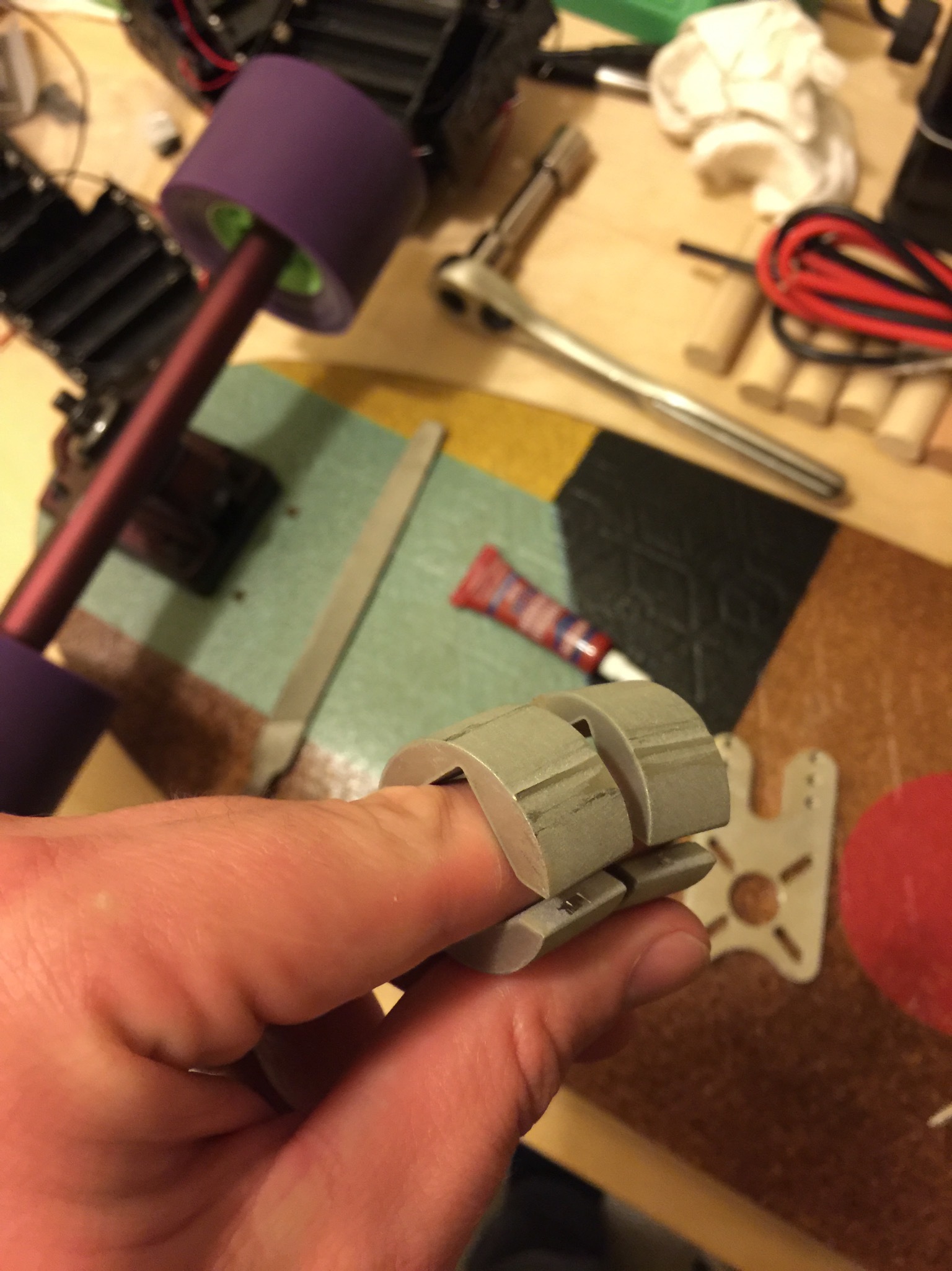
Next is the 32T HTD5 pullley and as you can see more burs from manufacturing
and along with that the diameter of the pulley is not quite right for the 32 teeth and the HTD5 pitch so as you can see when there is tension of the belt there is a bit of slack in a portion of the belt. this will cause premature belt failure and eventually the teeth of the pulley will begin to wear away due to the concentrated stress at the enterance and exit of contact. The next part are the truck adapters and while I like water jet manufacturing I would not consider it an acceptable as milled surface finish so again a file was needed to finish the part to get it to fit in the motor mounts. These nest two images shows the galling on the adapters from an extremely tight mount fitting and the non perpendicular circumference to the sides. However that all being said, with a bit of work everything went together well and I am please with the finished product.


Next up came the battery build, I decided to go with these 18650 sleds that were only $3.20 a piece and modify them. starting with the removal of the leads and parallel connections.
Then I added 14 awg solid copper bus wire in a configuration to make a 10S4P battery. It’s not show but I doubled up on the 14 awg wire for an equivalent 12 awg which is more than enough to handle the amperage and when checking the resistance of the connections it was below the tolerance of the meter so about .00002 ohms. Next I added braided protectors to the motor wires and heat shrank then ends. The heat output of the fets on the VESC gave me a bit of concern so more for peace of mind than anything else I added these little RAM heat sinks to each fet.


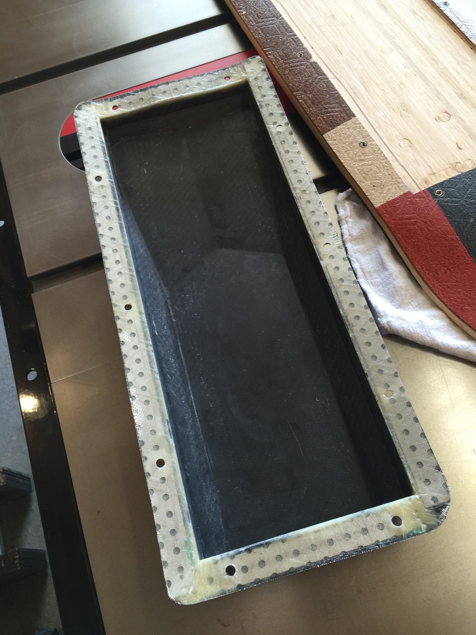
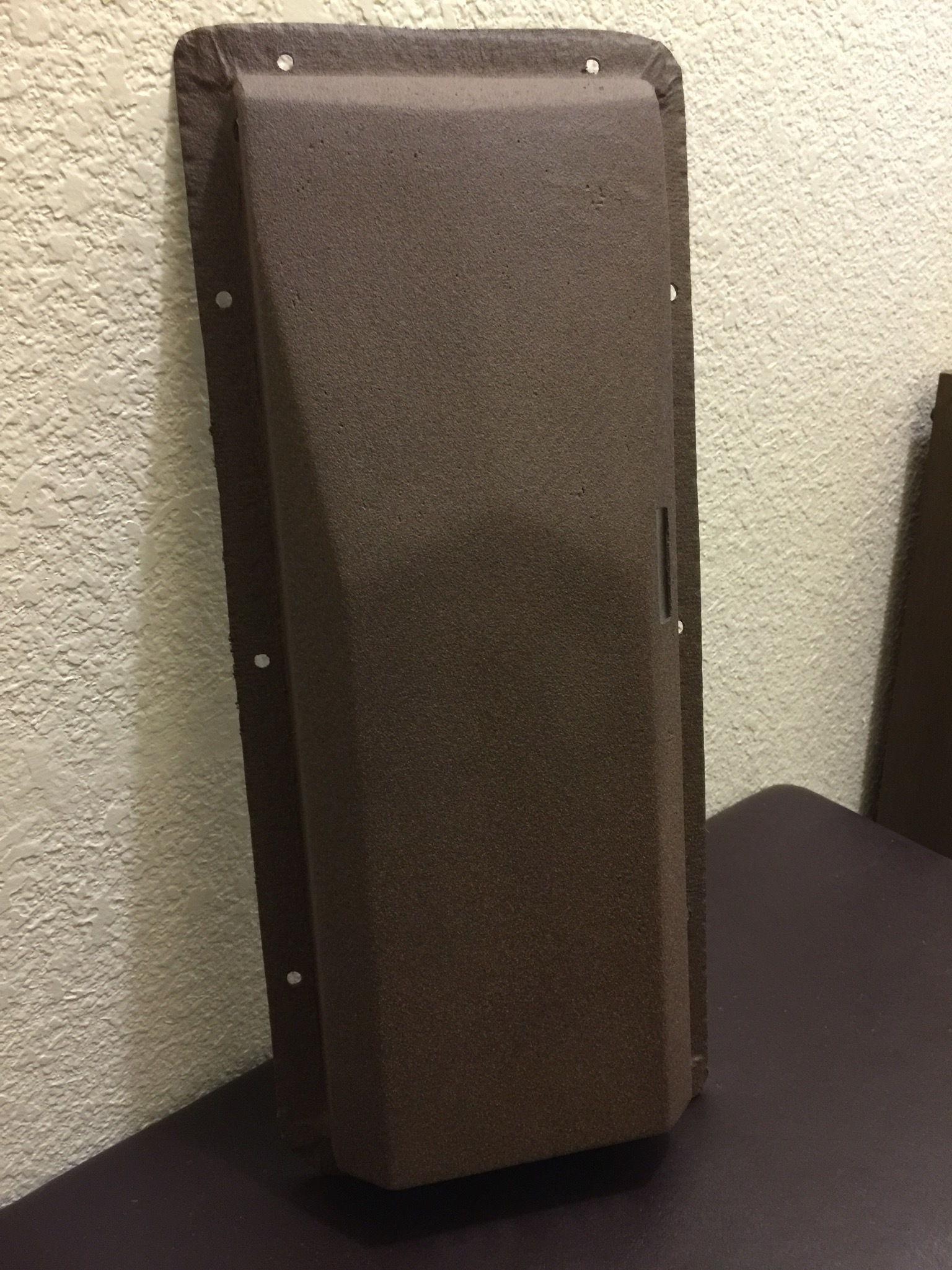
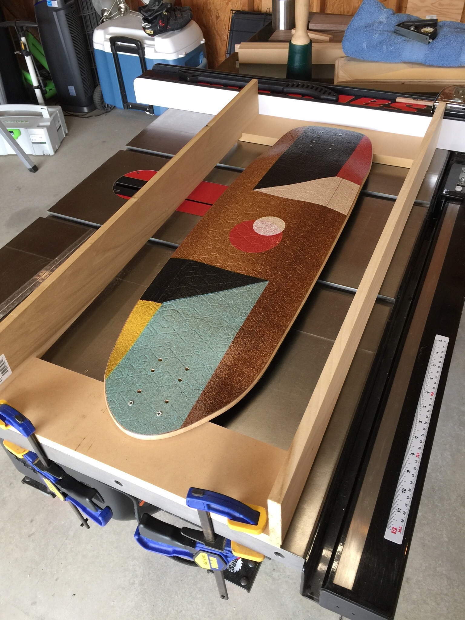
Next came modifying the deck to accommodate the battery, electronics, and case. I had to make a router sled so I could accurately route out a max 5 mil deep uniform surface to which everything would be mounted to. Once all that was done I tried my hand for the first time at vacuum formed carbon fiber molding. I’m not particularly pleased with the way it came out so in the next week or two I plan on doing it over and adding reinforcement in high stress areas such as fastener pass thoughs due to deck flexing. With the major fabrication done it came time to assemble the electronics, I added an additional lead to the Kama receiver antenna so it could be routed outside the case.


I then did an initial assembly of the electronics pack for a test fit and run to identify any potential problems.

After the first ride it became quite obvious that I was going to have to take greater steps toward vibration management. I noticed that due to the orientation of the battery cells, constant vibration could cause them to lower to the point of intermittent contact. I’m not ready to glue them all in place because as I mentioned before I’m not using a BMS so I want to maintain the ability to monitor and if necessary replace individual cells if I notice a problem. so I added carbon fiber panels and metal straps to keep everything in place. also notice I’m using an XT90 anti-spark switch and I’ve placed the Kama receiver away from high frequency switching amperage sources to minimize interference.

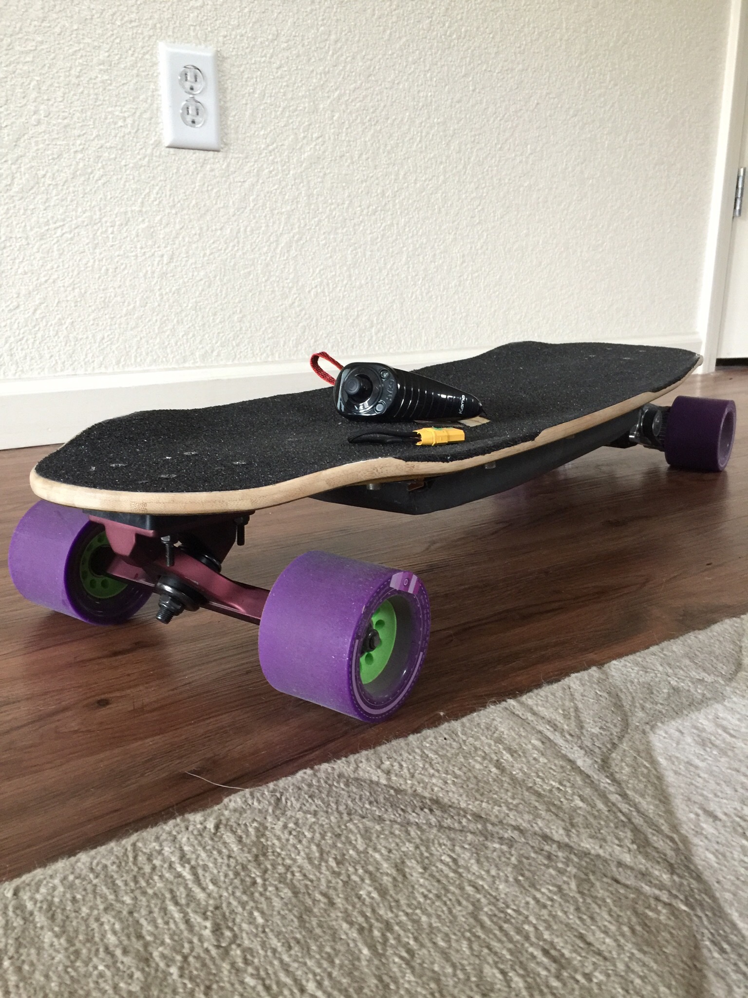
After all the here is the final result.

As I mentioned before I intend to redo the enclosure and I’m also thinking of switching to abec 11’s Thanks for reading and I hope this helps some as I have found help from the forums.