I managed to get everything working (homemade vesc), the board was moving with the remote (nothing on it), but when I put my foot on it and applied a small pressure, I found some lag in (that’s what I thought) the command transmission. And then nothing, even with my foot off. The red led was blinking and the board not moving anymore.
I connected it back to the computer and I had a ABS_OVER_CURRENT (-136amps something like that). I rebooted the VESC, seemed to be ok (no error showing up and correct current values), but now the motor doesn’t move anymore
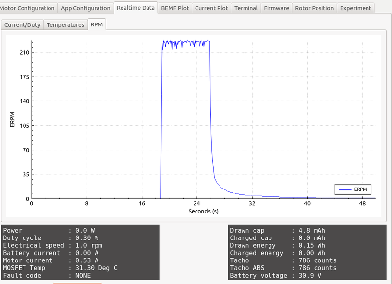
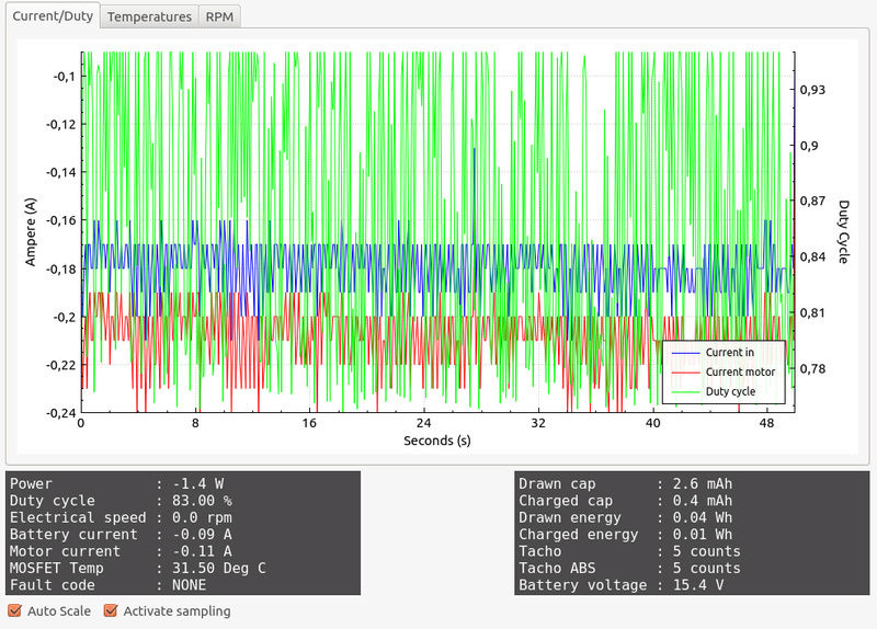
It’s like the VESC “see” it moving (the pikes is when I hit the gaz but the motor doesn’t move):
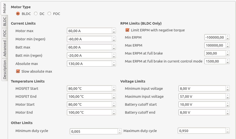
My motor conf:
When I run a motor detection it doesn’t move the motor and I get bad detection but no error in the real time data.
So close to ride it…
I checked the shunt and added more tin, don’t know how it could come from it. I’ll check the shunt line to the drv.
And the DRV pad is good, I made sure to solder it correctly (it’s my second DRV, I blew the first one either because I soldered a diode the way around or because the pad wasn’t correctly connected).
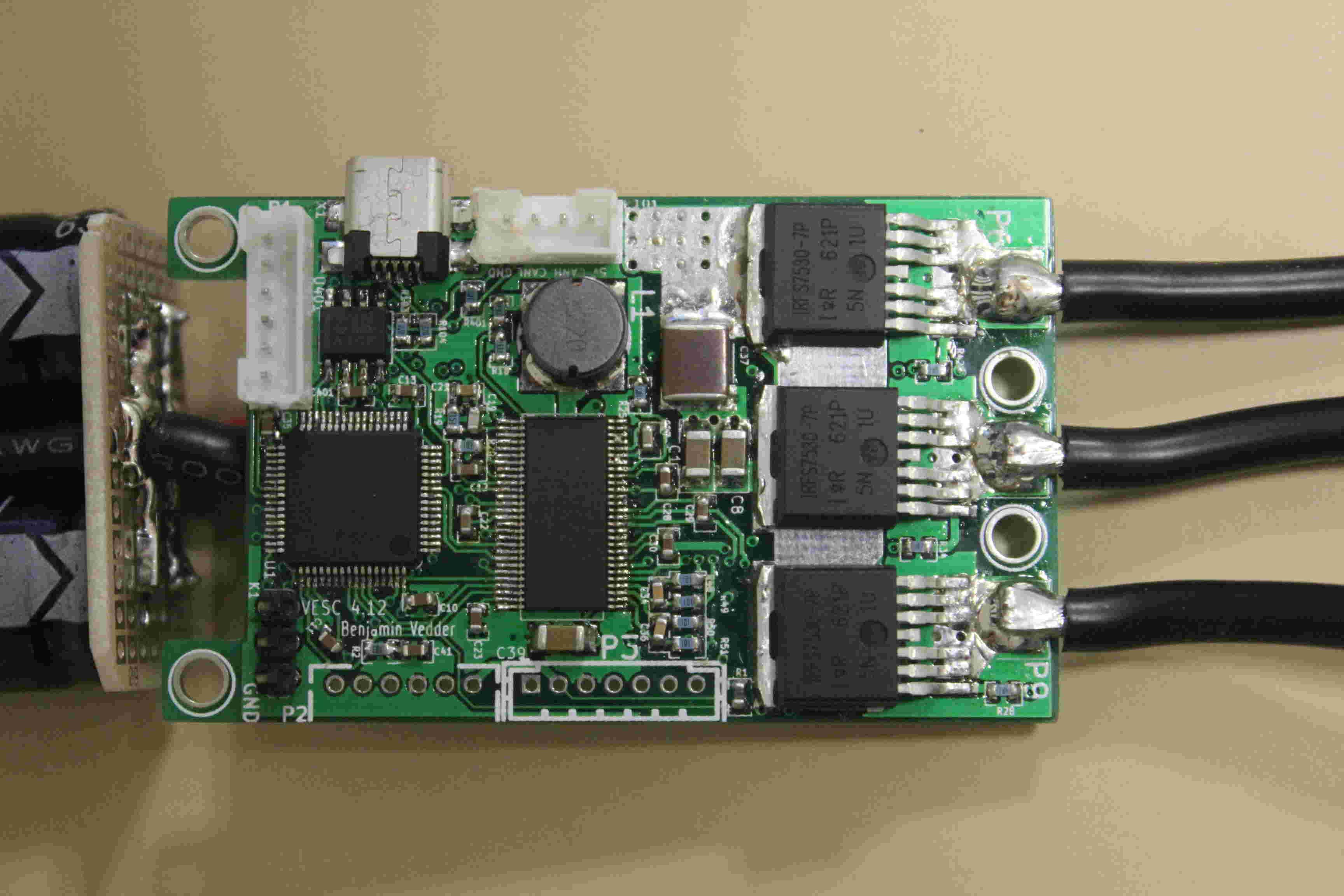
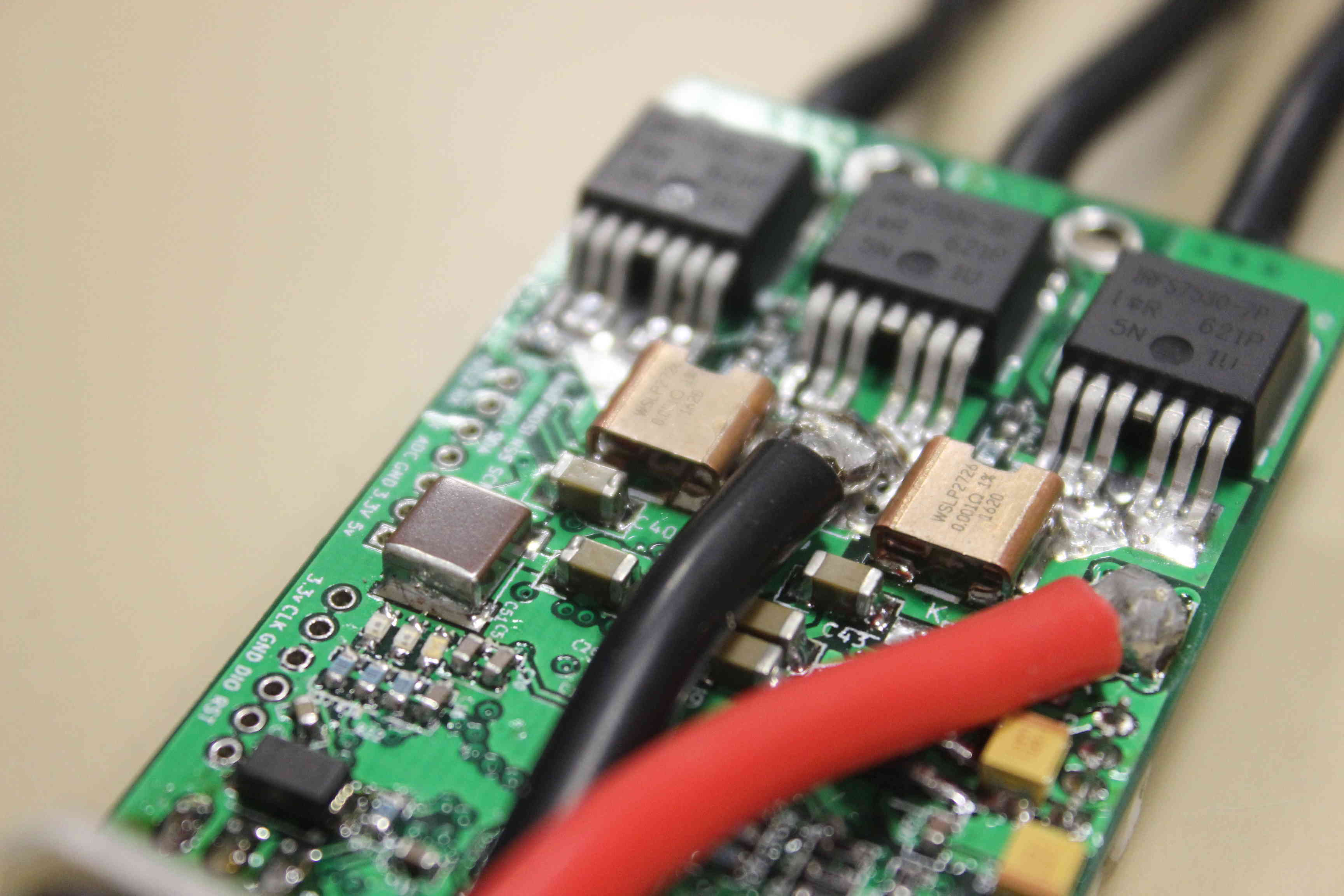
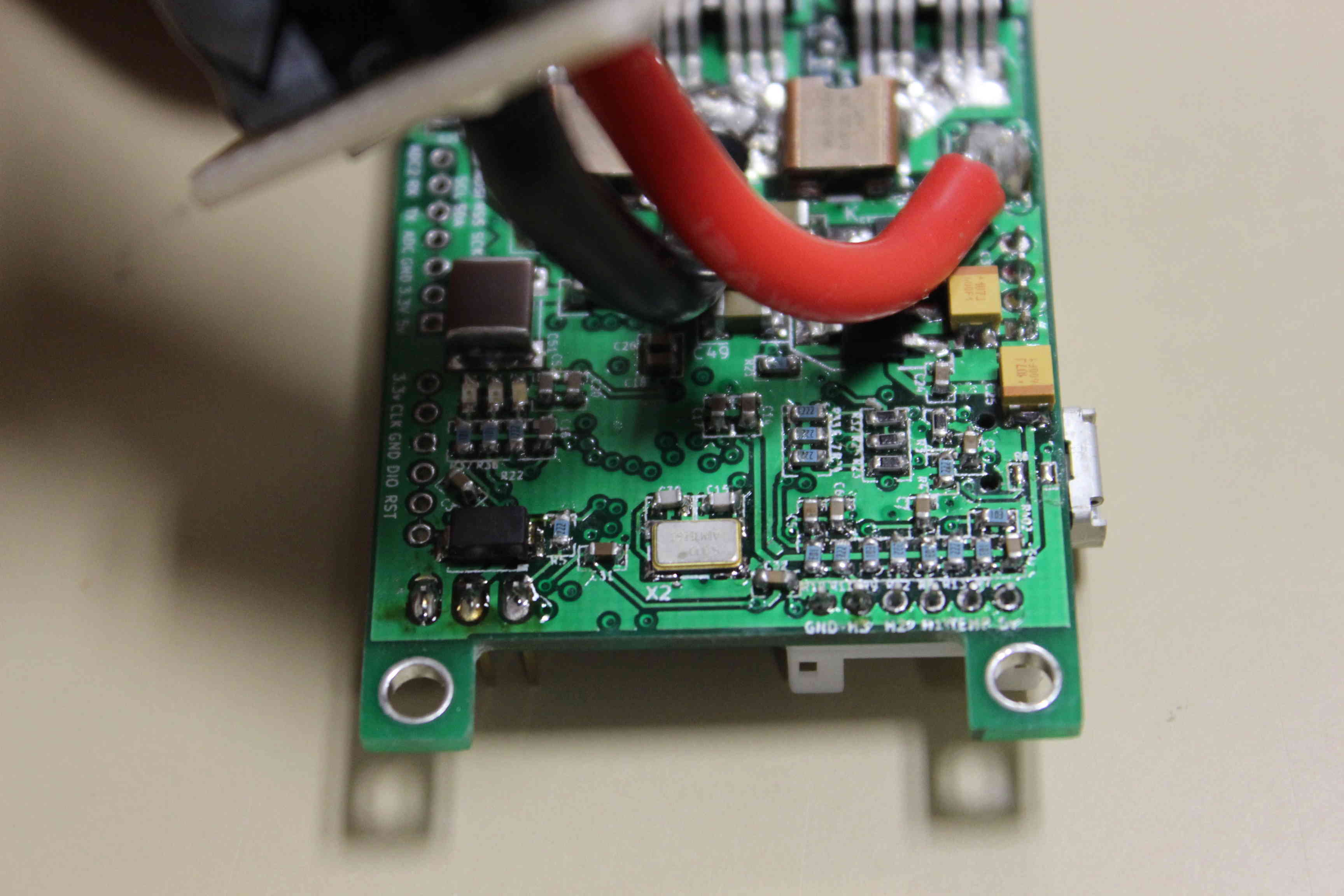
Here are the pics:
Could it come from the big caps ? I’m not sure the soldering is perfect (I’ll fix it tomorrow).
Other thing you can do is check the continuity of the drain-source of the fet to see if you have one that is blown. Same thing for gate-drain, must be high impedance.
@Blasto : I checked the shunt and they seem to be “shorted on themselves” as you said. I think my multimeter is no accurate enough and see it as a continuous line (here in red). Is it normal or should it see a resistance between the red dots ?
I don’t know what you mean by the drain-source and gate-drain. Could you please be more specific ?
Thats normal, accros the shunt there’s 5mOhm of resistance, you won’t be able to measure that with any multimeter. What i mean when i say short themselves, is the small leg is short with the big leg. But i dont think this is the case.
I had this issue when I had bad connections from the FETs to the Motor. It was evident when I inspected the plugs and they had burn marks from the arcing electricity. Perhaps ensure that you have a solid connection that can pass high amperage/voltage through?
I tested as you showed. Here are the results:
-in position 1 (picture 1) I have 0.431v value
-in position 2 (picture 2) I have 0.572v value
If I put the probes in the opposte way, I do have OL but not instantly, it “slowly” raise up until it displays OL.
However, in resistor mode, I can read the same value in both position (reversing the probes) Not good right ?
Values:
-in position 1: 41kOhms for the for the two fets of the right, 5MOhms for the third one (the one tested on the picture).
-in position 2: 38kOhms for all fets.
Those values are the same for the fets on the other side of the PCB.