{COMPLETED} $800 CalBeast 10S 6365 170KV Volador Build

Sup guys!

This is my fourth build in total now. I have 2 boards for friends so far and one for myself. This one is for another friend that attends Cal Poly SLO. Goal here was to fit very closely within the $800 budget range and use his existing board {Volador Amazon Deck} to put it on.

I’ve completed this build and the final pictures are at the bottom of this thread. It’s a long read but I decided to heavily document this process so others could learn from it!

20190103_162652

Thanks @hyperIon1 for hooking it up with the Maytech 6365 motors and the quality Bestec BMS.

The rest of the build list is included below in this excel document! Feel free to look and/or ask questions. I will be updating this build as the parts come in.

CalBeast $800 Board {Direct Excel Sharing link!}

1 Like

Getting pretty good at doing these loop keys. Heres the great looking one for this build. 20181218_182557

Behind you can see the MadMunkey remote mod that I did. It came out awesome in my white 3D printed case. These always take way longer than I expect them to. Probably about 3 hours to complete the remote mod with all the annoying soldering and then troubleshooting the potentiometer that I accidentally broke.

20181218_163046 20181218_163056

Also pictured are the batteries. I went with these Nanotech ROAR approved ones. They were on a huge sale, 22 bucks down from 36. Originally I planned to do the pack like this but ended up slightly changing it once I looked closer at the wiring required. These packs come with disconnectable leads and make it super easy to wire them together. I barely used any additional wire in this build.

20181218_163044

Wiring completed with the positive and negative out as well as the balance connectors.

20181218_174213

3 Likes

I assembled the reverse mount truck mouns and the wheel pullies, only to realize that when I asked DIYElectric for the reverse mounts on my order instead of the front facing ones, they had forgotten to provide the correct length of belt for the reverse mounted motor position. I ended up emailing them and they were able to send the correct size. Took about a week for them to arrive from message to receiving.

20181218_232959

Fast forward some hours of work later, all connectors are soldered onto the wires and the Bestec D140 10S BMS. I used an XT90 male for the loop key obviously, and then a female XT-60 for the charging port. The XT-60 connectors are very robust and can support more than enough current to charge through. In the past 3 builds I have done, I used the male XT-60 for charging, as it kept the whole connector inside the enclosure, but it makes it very hard to grab the female connector to pull it out when unplugging it from the wall. The female side has a very small grippy part. This is why I switched it to the male part on the board. This will later be pictured in the final images.

Also connected here are the two Flipsky VESCS that I got from Alibaba. I chose to go with these instead of the DIYElectric ones because they are considerably cheaper. We are running 170KV motors on 10S here and there is no way they will ever get close to 60K ERPM. I think these will be robust enough running only in BLDC mode with standard settings. We will see how well they last over time but I have heard enough positive information about them that I trust to send them out in a build. They help keep the cost down a lot (two for $104).

20181220_211022

The BMS balance wires are not yet wired up to the battery balance connectors quite yet, but that is completed later.

2 Likes

Hard to see here but I completed the wiring for the balance connectors (triple checked the voltage order before plugging it into the BMS). I ended up using some 3S JST plugs that I had sitting around because I have like 50 of them. I simply pulled the extra small wires out of the plastic plug housing and used a knife to cut off the second finger on the battery side of the connector. Here’s the BMS diagram that I used to wire the Bestec D140 BMS. it is a little odd that they split the balance connector into two parts on my particular BMS but it works.

The red marks on the connectors were the wire numbers that I wrote on there, since they were counter intuitive to what I thought they would be.

20181230_171625

Here is the completed battery pack, ready to place into the board enclosures once I make them. I used fiber tape to reinforce the pack and tape down the BMS and balance wires. You can see the charger plugged in at the bottom, this is a standard 10s li-ion charger I purchased from Amazon and then put a XT-60 on yet.

20181230_182339

The wiring for the board is also now completed. Everything works great and the motors sound awesome in BLDC mode.

20181230_171629

2 Likes

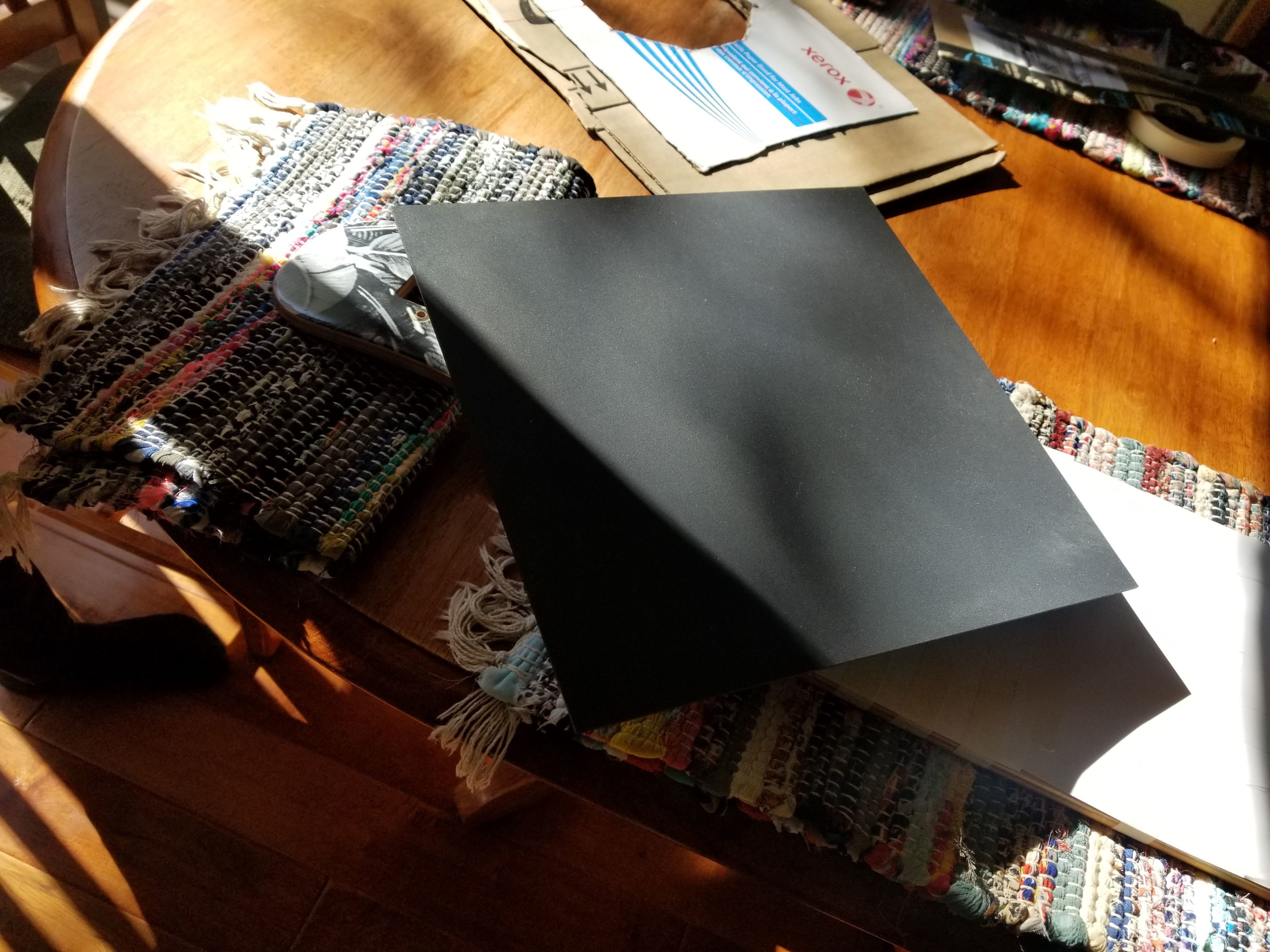
The final part of this build was to make the enclosures. For this portion I chose to use 0.08" Kydex. Kydex is an awesome material and is extremely strong. I got these sheets from Amazon and additionally chose to purchase a Porter Cable heatgun that was essential in completing these enclosures.

https://www.amazon.com/gp/product/B004Q04X44/ref=ppx_yo_dt_b_detailpage_o00_s01?ie=UTF8&psc=1

https://www.amazon.com/Plastics-2000-KYDEX-Sheet-0-080/dp/B077S64M76/ref=sr_1_1?ie=UTF8&qid=1545450889&sr=8-1&keywords=Plastics+2000+-+KYDEX+Sheet+-+0.080"+Thick%2C+Black%2C+12"+x+12"%2C+2+PACK

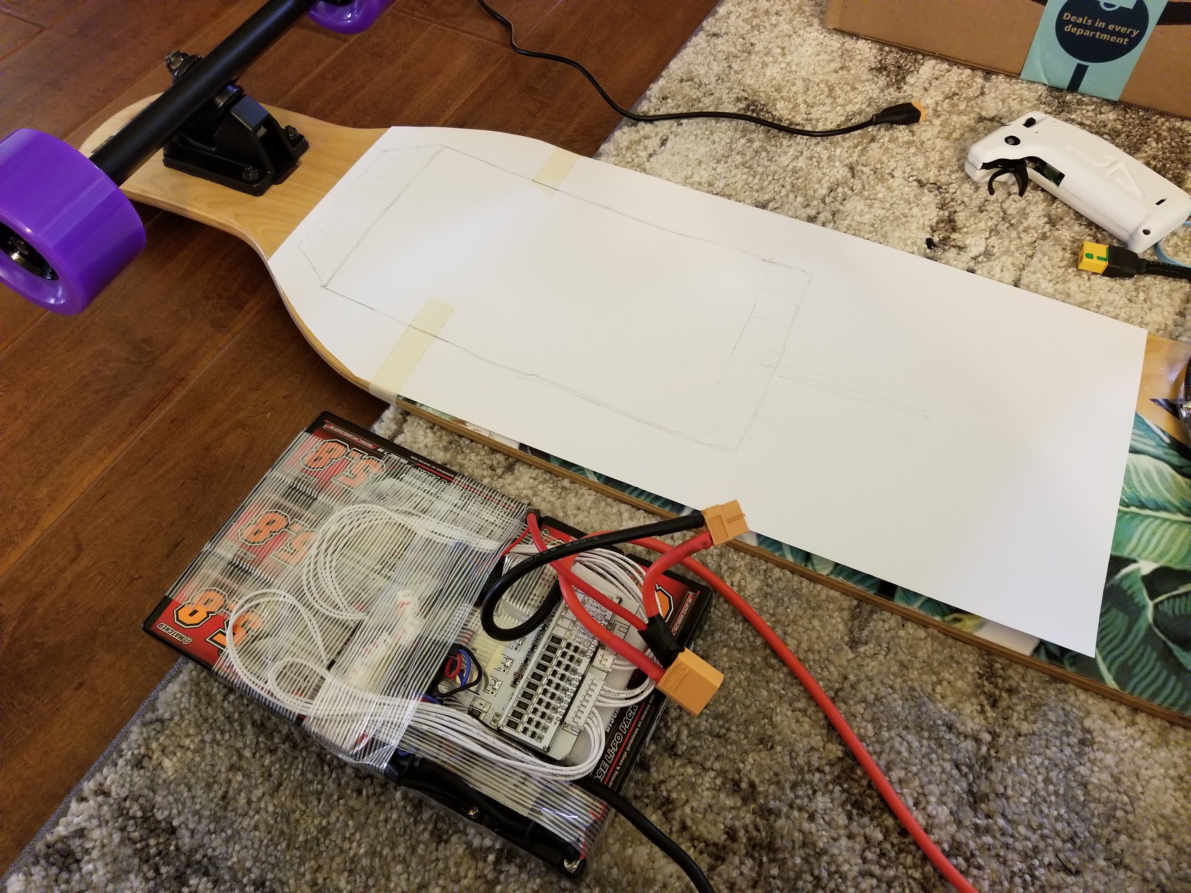
Got two packs of these Kydex sheets. I used paper on the longboard to trace out the approximate size for the battery pack enclosure, leaving room to mount the loop key connector and the charging port towards the bottom. I then measured these and approximated how tall I thought it would need to be. These sizes turned out to work great. I used two sheets for the battery enclosure.

After quite some work, I had a mold made for the front enclosure. I used some planks of wood that I got from the Home Depot scrap pile for free. I used a wood base on the front angled part and then some cardboard for the top. I had heard that cardboard can compress quite a bit when making these but I figured the two sheets for the additional thickness on top would be alright.

I glued these together with hot glue, but if I had more time I would have used wood glue instead. When I was gluing it I placed it on the board to make sure I got the curves correctly.

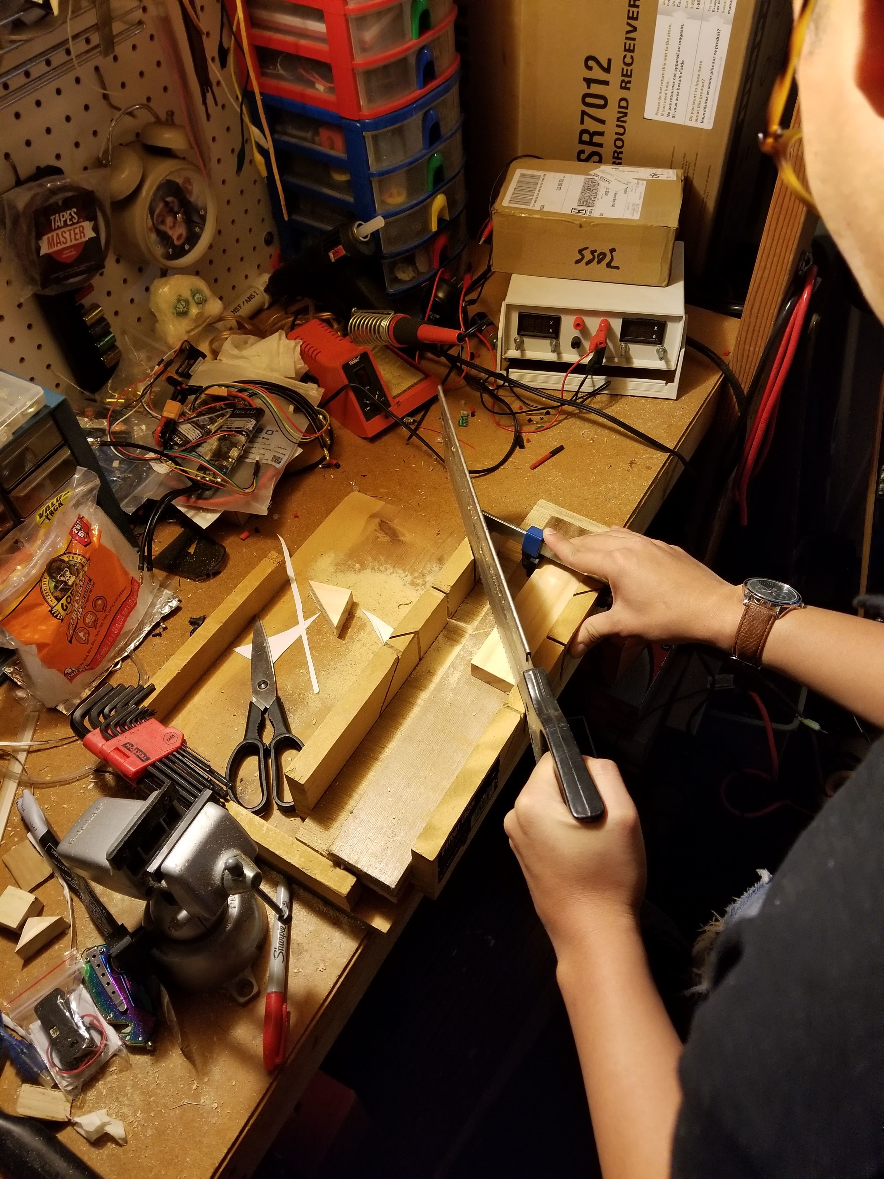
in a similar fashion, I made the mold for the back enclosure. I used a circular saw and a backsaw with a cutting box to do all of the woodwork for this. Additionally, a harsh rasp was very useful for shaping both the Kydex outline and the angles on the wood.

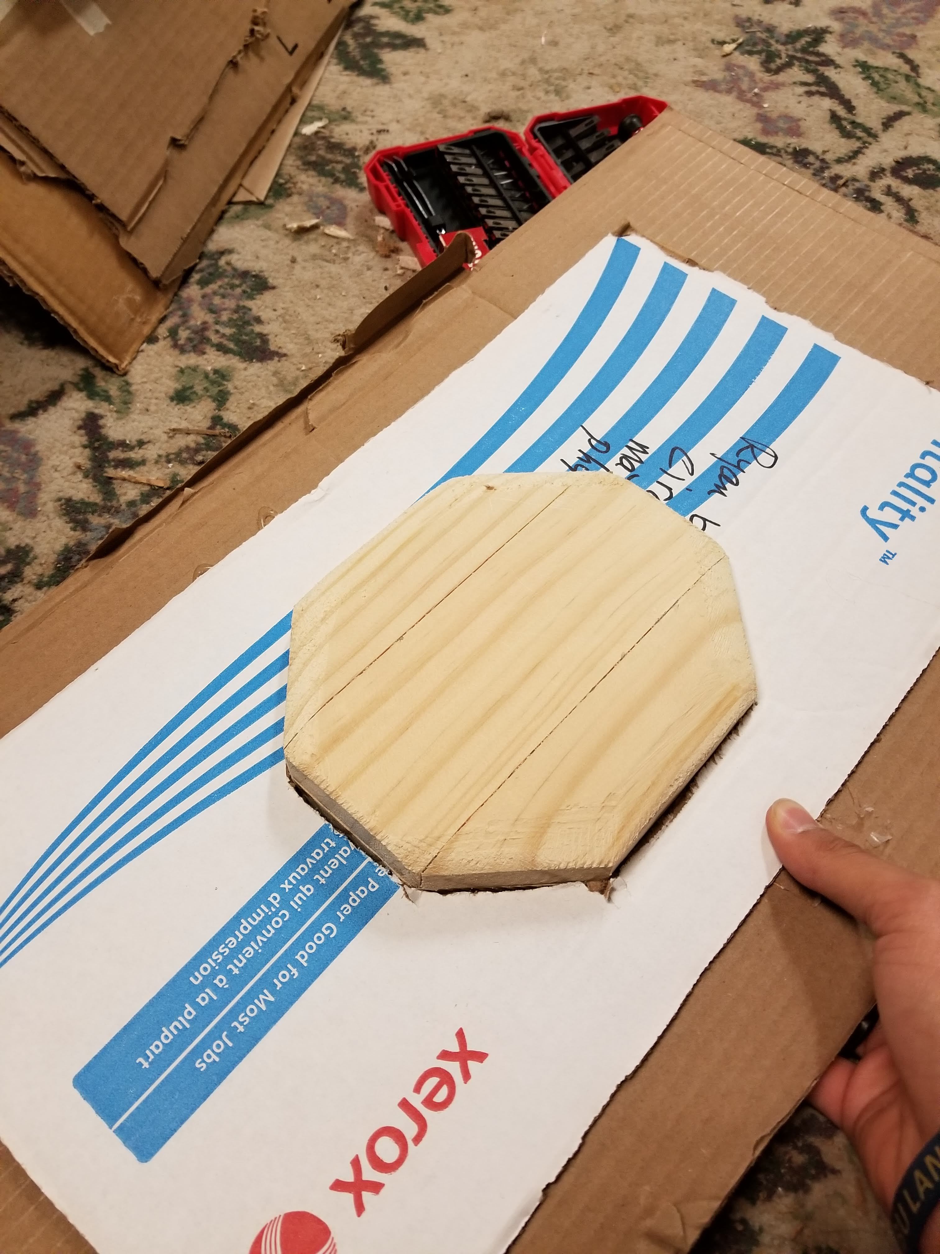
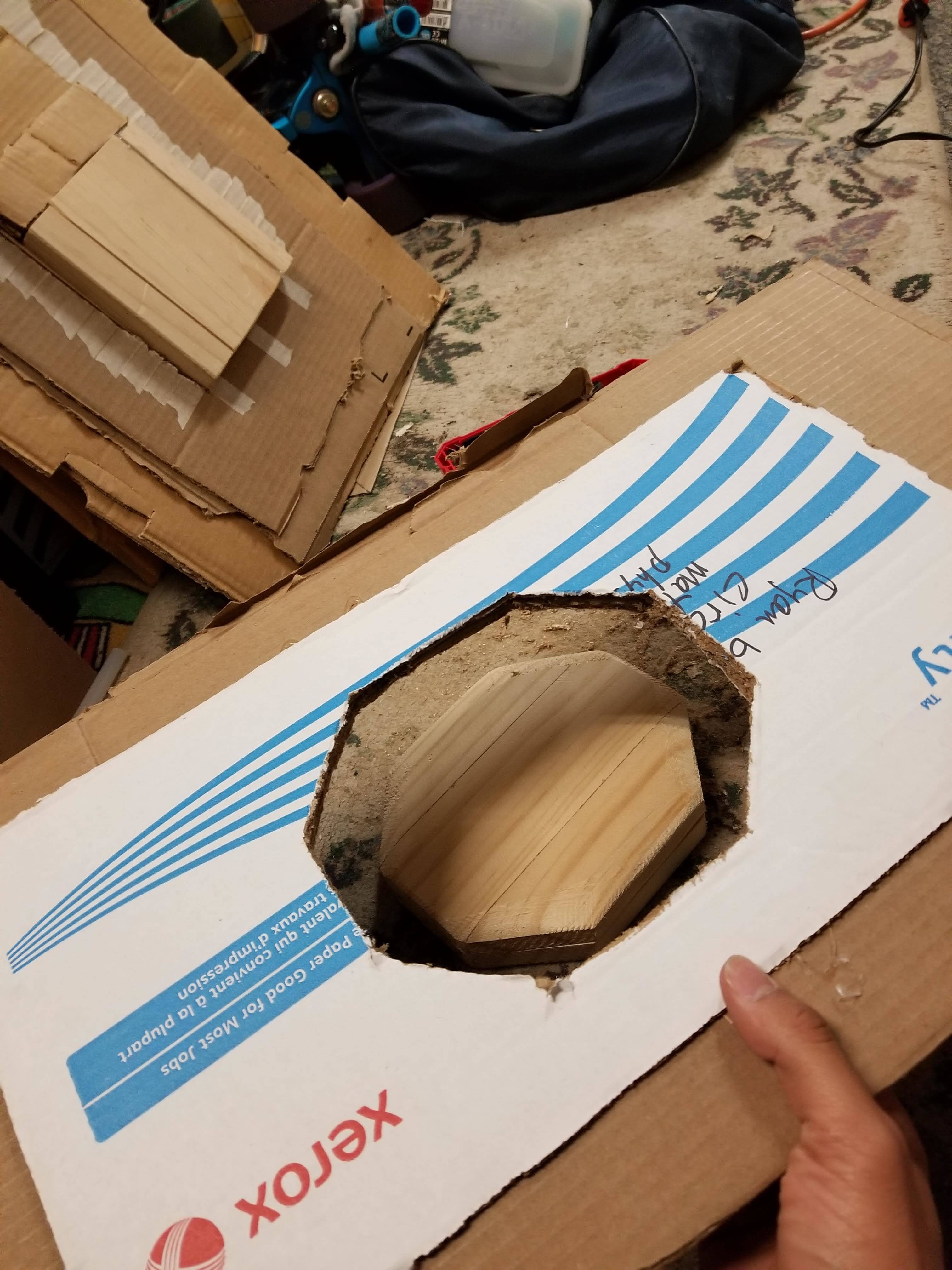
After creating the molds for the front and back, unlike most people who make Kydex enclosures, I was not able to find any strong foam that I could use to push down the Kydex, so I made cardboard positives. Here is the mold for the rear enclosure and its cardboard positive, along with the front mold positive.

These positives are all layered several layers thick in order to have enough strength to stretch the Kydex over the molds.

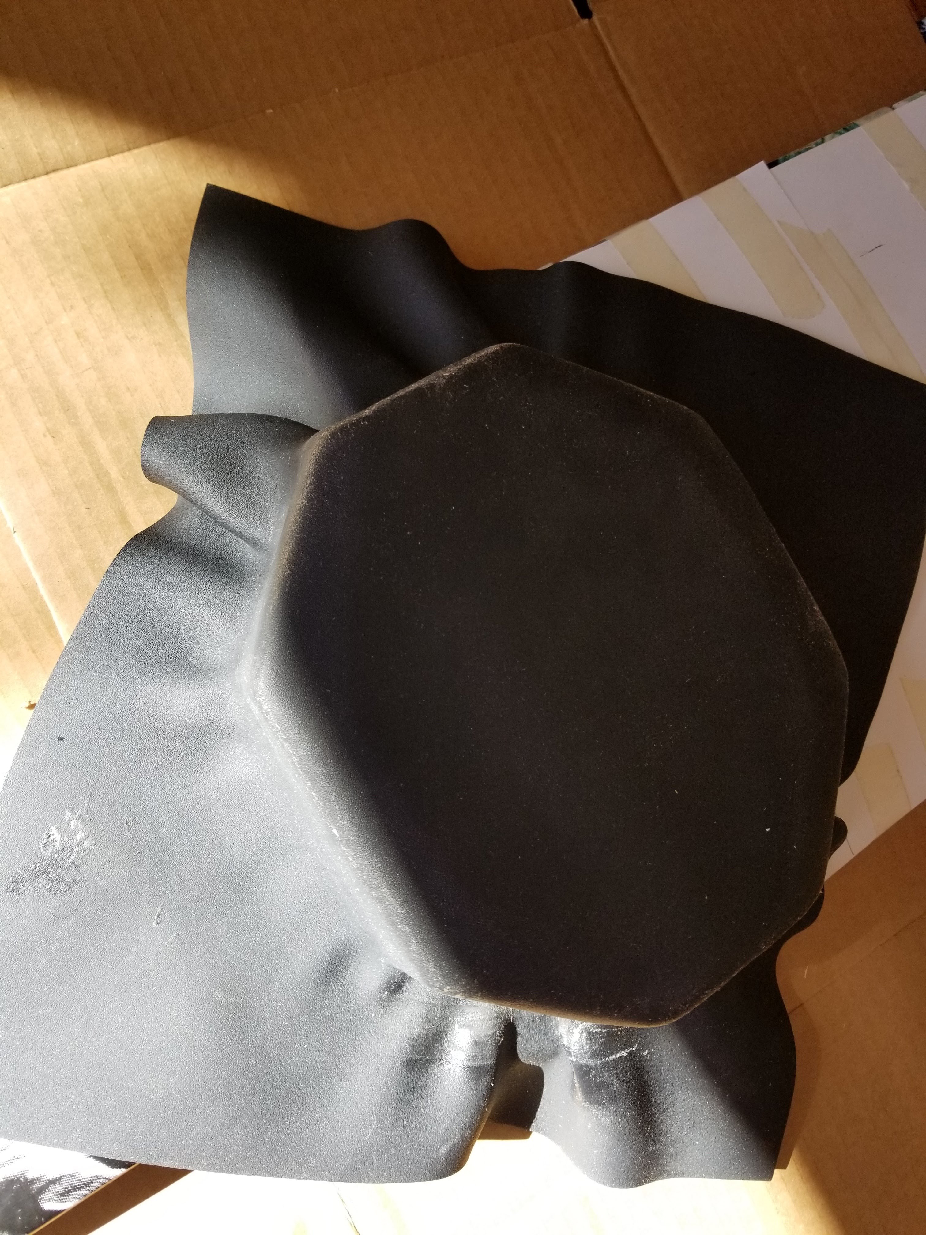
Moving on to the actual difficult part. I used a normal kitchen oven to heat up the Kydex sheets on a piece of cardboard. I set the oven to 350 degrees F on convection to heat it up and then changed it to normal bake mode when I set the plastic in so the fan wouldn’t unevenly heat it. Sidenote, the plastic gives a faint smell but it dissipates pretty fast and does not stay in the oven. It took about 7 mins to get the plastic to its soft state. The first one I did was the rear enclosure. This proved to be the hardest one by far, due to all of the angles on it. Looking at it again, going with larger angles and less of them would have made it easier, but I am still pretty happy with the end result. I was worried about one sheet being able to cover the entire rear enclosure, so I estimated and decided to turn it 90 degrees to press it on. The wooden mold is glued down to the paper, and the paper is taped to the board so we could push it in different directions.

After the first press, there were lots of ripples in the Kydex, seems pretty unavoidable with a shape like this.

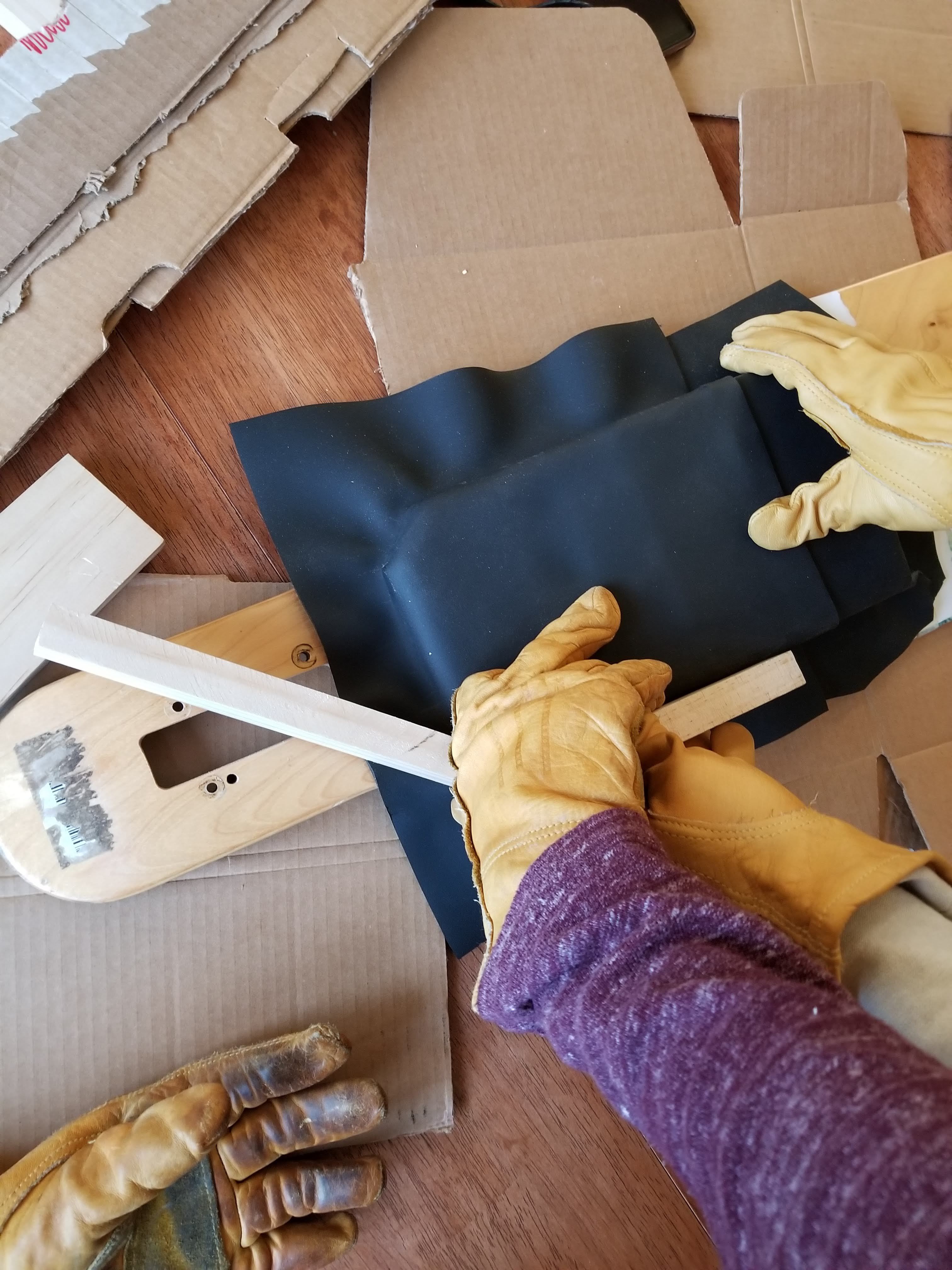
At this point, I switched to using the heat gun to heat up parts of the enclosure that were rippled and pressed out the ripples with some scrap pieces of wood that we had from making the molds. This process was incredibly time consuming and probably took 2.5 hrs to make this rear enclosure with 2 people working.

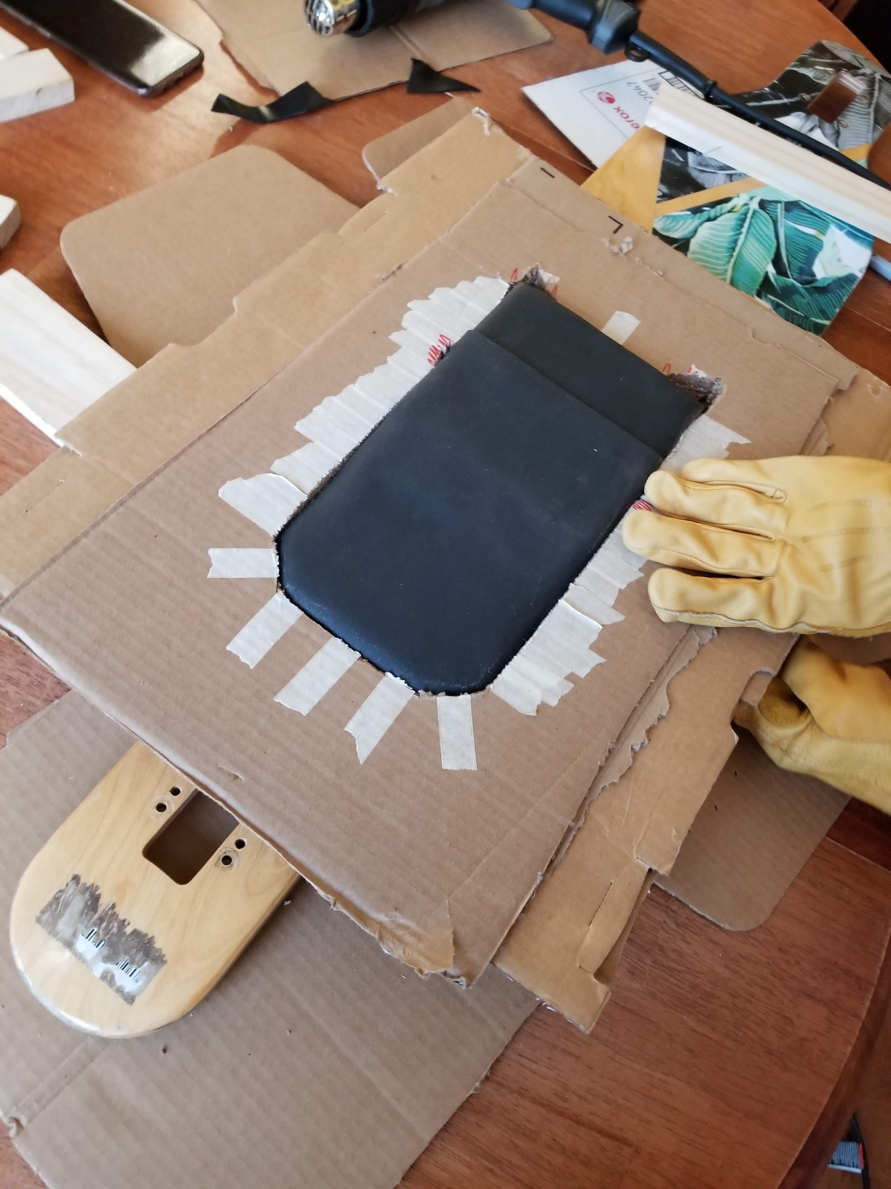
Moving on to the front enclosure, I started with the smaller piece, which would be covering the rearmost part of the battery pack. The first press went pretty well, however, this time I heated the plastic 3 seperate times in the oven to start working the shape into it.

After fixing up the rearmost part of the front enclosure with the heat gun and wood scraps, I then pressed the next piece of Kydex over it. The first press looked like it went pretty well, and it actually was pretty decent. This was probably due to the long straight edges and the fact that the front part with the angles was not nearly as tall as the octogonal back enclosure.

Fixing the front did not take as long but since there were two pieces, it still took about 2 hours to complete.

After all the arduous labor, the two enclosures were finally done and looking pretty great.

The final things to do were to cut out the hole for the battery meter, the charging port and loop key, and the holes for the motor wires in the rear enclosure.

After cleaning up the edges with tinsnips and a rasp, I applied some weather stripping around the edges of all the enclosures.

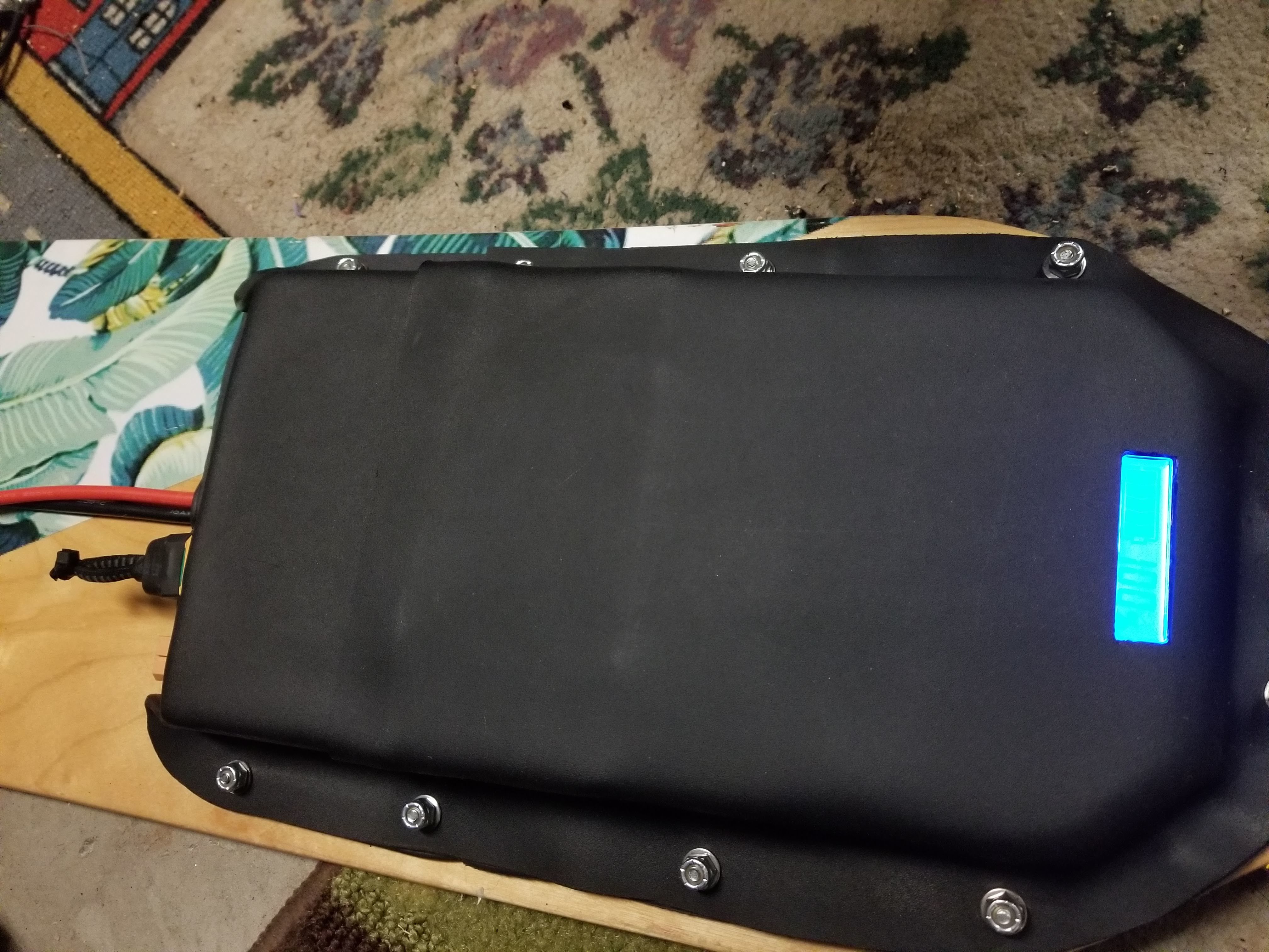
Front enclosure turned out amazing. I used #8 screws in attach it to the board, and heavily padded the batteries on all sides with weather stripping. The battery meter is heavily glued in.

Taped the VESCS together with fiber tape and padded the enclosure with weather stripping

I simply let the wires that travel from the front enclosure to the back enclosure go under the weather stripping and that worked out fine.

6 Likes

Final pictures! I’m very happy to be done with this build and I’m proud of the final result. Excited to do the next one this summer!

Snapchat-751054010

20190103_162258

20190103_162633

20190103_162652

20190103_162710

20190103_162736

7 Likes

Thank you thank you thank you!!! You just saved my kydex enclosure project. I don’t know why I didn’t think about using positives lol but I didn’t. The enclosures turned out amazing bruv. Going to try and save the first attempt. Though if can’t, I ha e two more sheets to get it right lol.

2 Likes

Ah no problem man I was really hoping someone would benefit from my work haha!

I love how they turned out too. Super sturdy. Don’t forget you can stick it in the oven again to mostly reset it. Also having two people helps.

1 Like

Studio living lol. Oven is just big enough to put a sheet in but I dont have a heat safe tray to… Wait. I can use aluminum foil for a tray. Awesome! Now I can definitely save the enclosure lol. Glory be to you good sir

3 Likes

I used a sheet of cardboard, 350 degrees isn’t hot enough to do anything to it. :stuck_out_tongue:

1 Like

So what temp and for how long in the oven?

If you scroll up and read, I did mention that, but I did 350F for like 7 to 8 mins, I just guessed and checked by lifting the corner until it was nice and “floppy” for lack of a better word.

lol Was getting excited and just skipped the first half of that paragraph lol. So any side note tips?

Lol you good. Just work quickly and you definitely need a decent heat gun and gloves. You’ll need something to press against it and hold to fix the ripples too.

Very nice build. Try those flipsky 4.12s on FOC. you be surprised. I am running 190kv 6374s 10s4p on them and they seem reliable so far albeit only 50km or so.

Good job on the battery and enclosure. I might try these 2s2p hard case batteries :+1:

1 Like

I mean considering it was more or less for a client I didn’t wanna risk them failing, if it was my board I would probably try that.

Thanks though! The batteries were a great deal