Hello my friends!
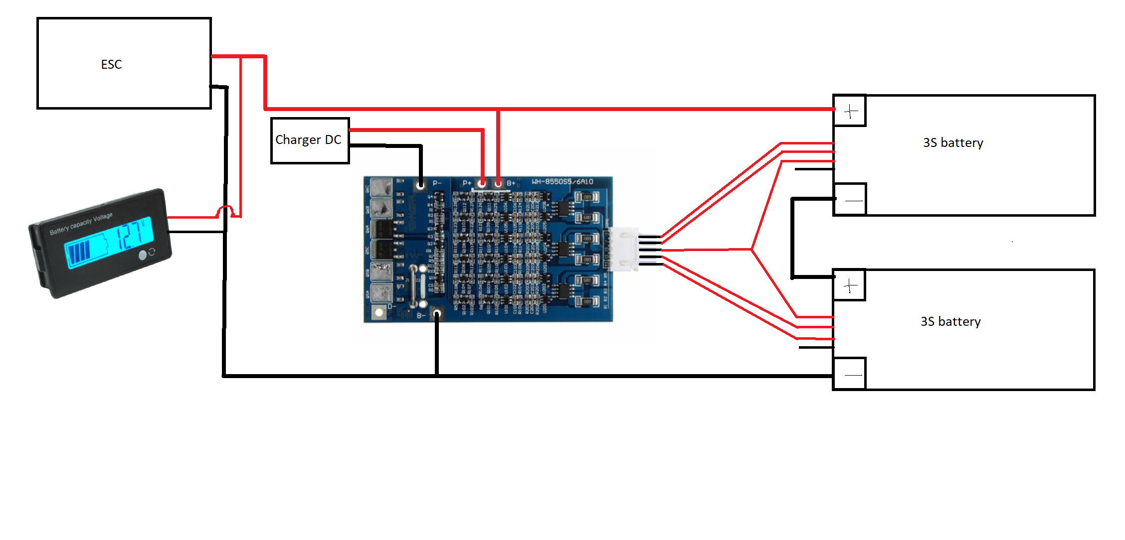
i’m new in this forum and this is my first topic. I need your help: i like to build my own electric skateboard but i don’t understand the wiring of the balance cables.
I got a 6S BMS with five pins and two 3S batteries with both four pins - how to wire it together?
Five pins only on the BMS is because it only carries the between cells connections and the ends of the battery packs are connected to the b+ and b- making a total of 7 conections.
I already made a diagram and it would be very awesome if someone could complete it! 
Another question is if the voltage indicator is wired on the right place?
Not sure about the balance wires, but make sure you hook up your voltage meter after the switch. If not it will drain power from your battery even If its not turned on
Do i have to wire a second switch between the batteries and the BMS? There is already one switch on the ESC, does that mean that i need two power switches?
Is that correct? What happened with the two ground wires of the batteries?
I think the balance wires are right, but i’m not sure… @barajabali may know? About the switch on the esc, What esc are you running?
Hmm… If i were you, I would have made an loop key. As the voltage meter is supposed to go between the esc and switch
The wiring diagram is not correct. You need to connect the black wire from the battery on top to the 3rd pin on the BMS. You do not need to connect the last red wire of the battery on top since that is already connected to the BMS (thick red wire)
Thank you very much for your help! But i am a newbie and english is also not my mother tongue (i am from germany). You would be my hero if you edit my wrong diagram and upload it here? that would be awesome!
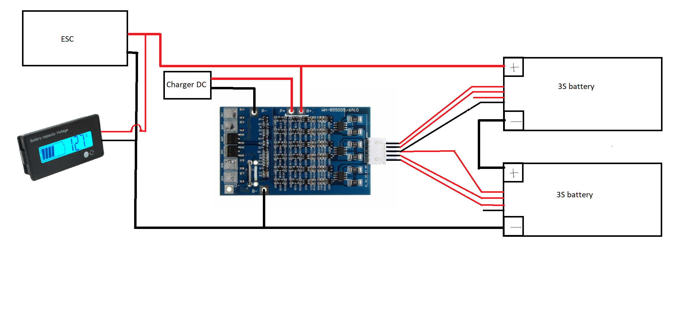
Is it correct now?
Almost correct  Move the top two wires on the battery down one step. And you don’t need to connect both the red and black wire to the 3rd pin.
I second that it is correct now. @ReeCorDs what tool did you use to draw the diagram?
2 Likes
@pat.speed Thanks for your help! I am simply used Paint  @NiTroNooB Thank you very much! And the three cables which are not connectet are just useless? So i do nothing with them
I have two other questions if it’s okay for you
-
what for a charging cable do i need to charge my board? How much volts and amps? I will use a DC female power adapter.
-
where i have to connect my battery capacity tester on the ESC? I’m using this one:
You need 25.2v to charge the batteries and you can use any connector you want. I don’t think you could use a volt meter with that esc because the switch is wired into the actually esc. You would need a separate antispark loop key or on off switch before the esc
25.2v and 2a is correct?
And for what are these two black and red wires on the esc? They are not connected to something. I mean not the thick ones
They are for powering an led button
How many amps do i need for charging?
No more than 5. Depends how fast you want it to charge. Most people use 2 or 4amp chargers
Okay, i will buy an anti spark switch. but i only want just one button to power my longboard on. when i simply remove the switch from my ESC and i wire the anti spark switch between ESC and battery, it should work, right?
And after this i can wire my battery capacity indicator between switch and ESC