-
yep, I have been using it for a while now. It works great. Here is the updated list
-
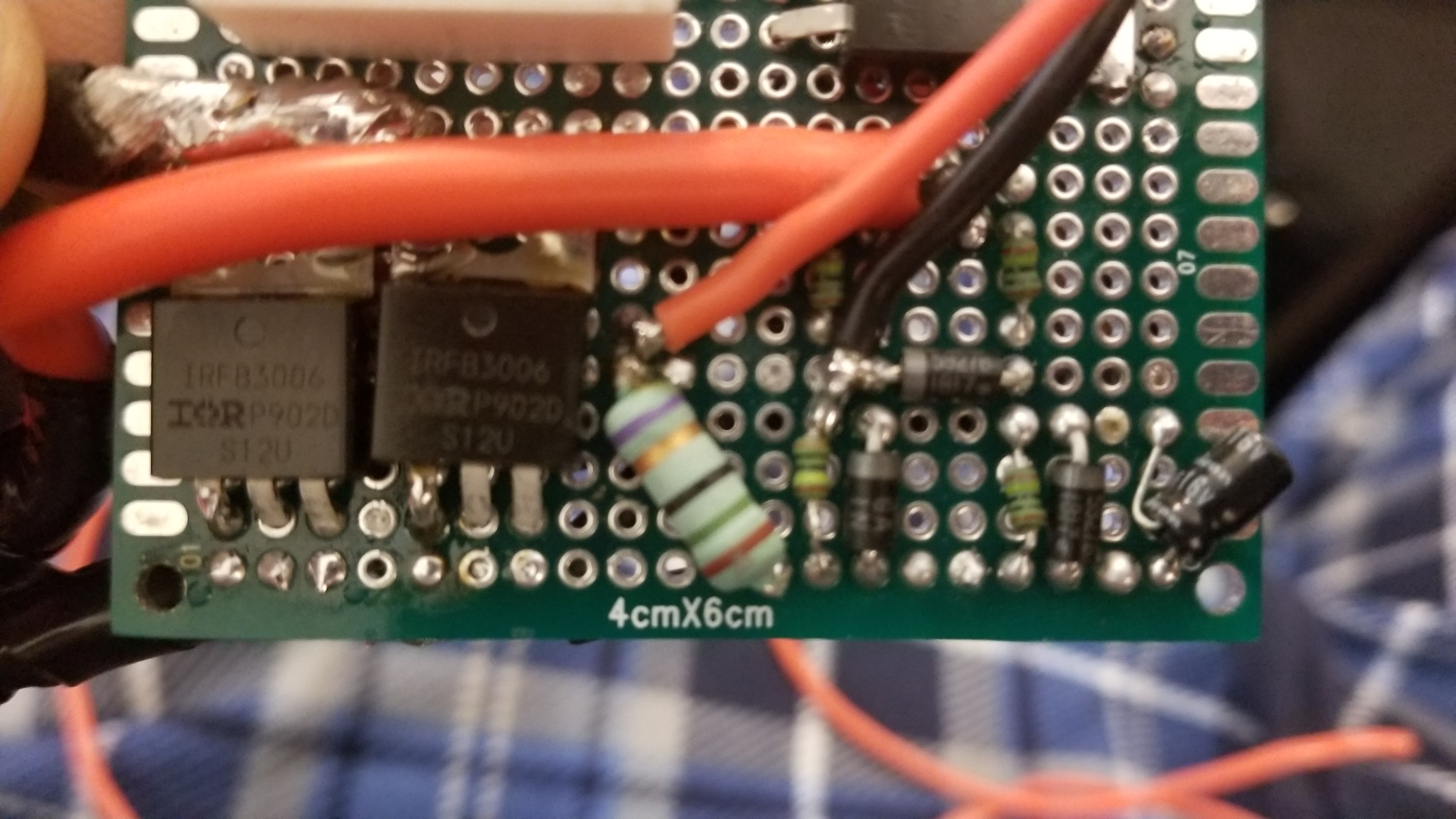
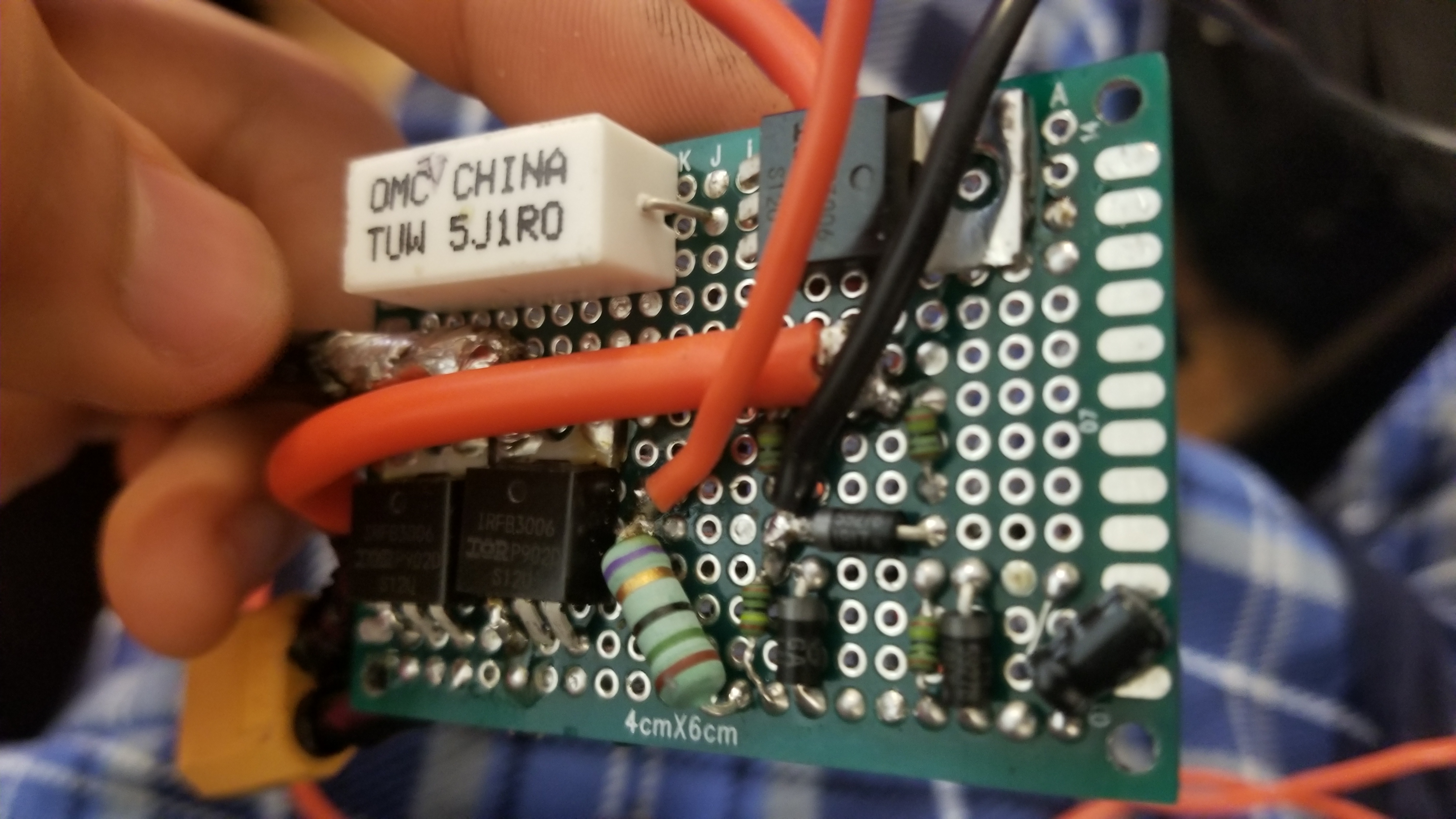
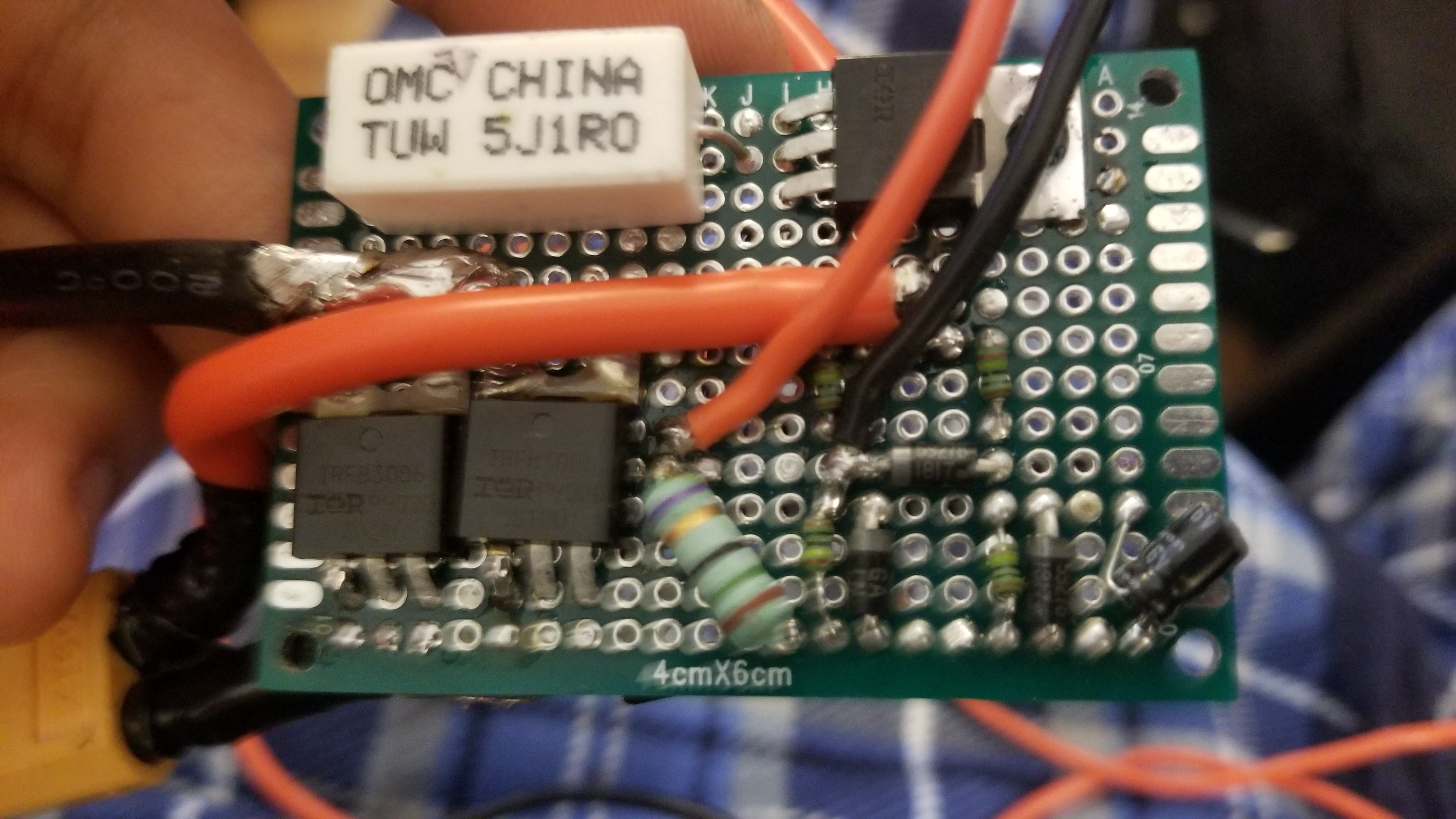
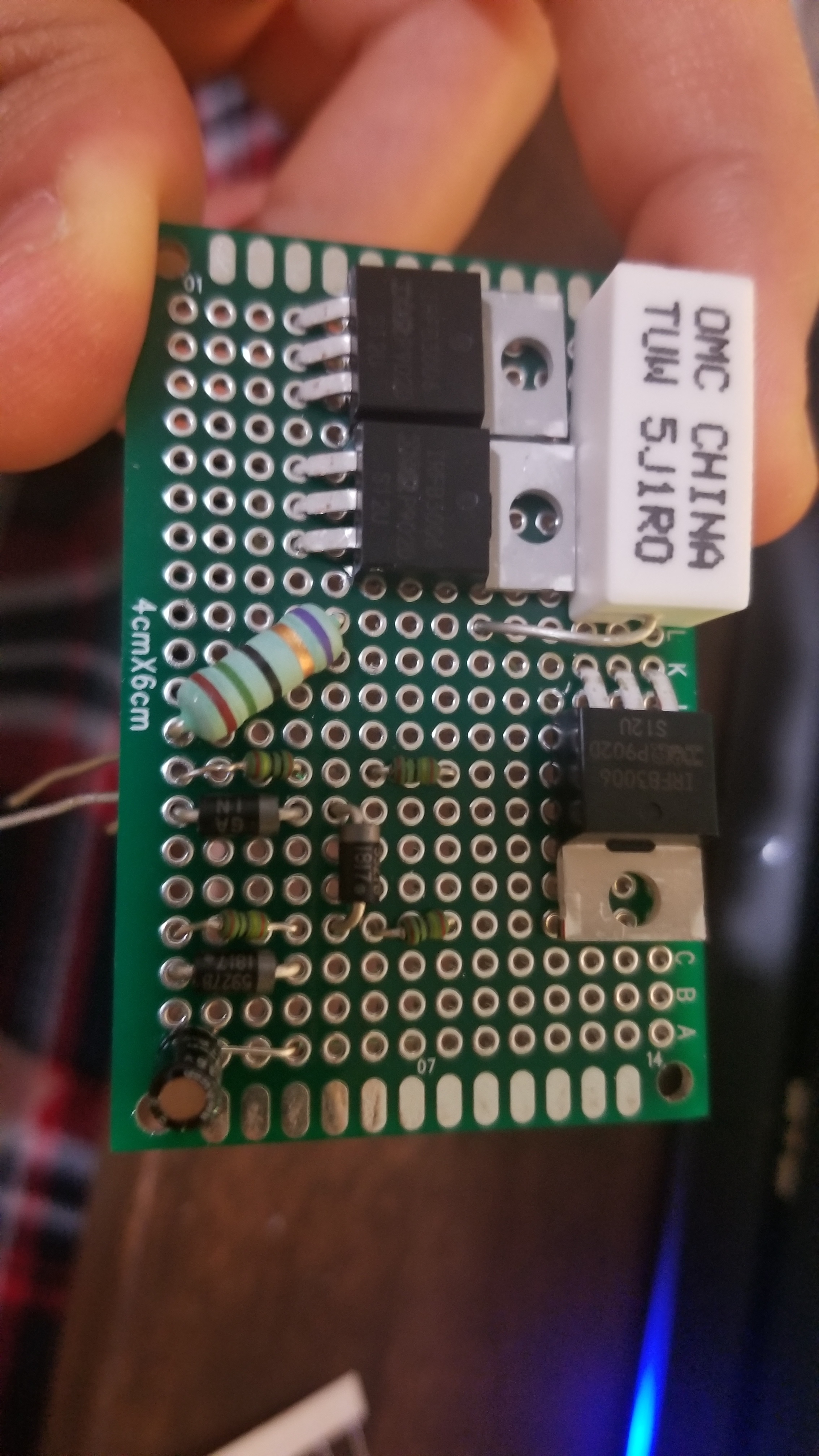
• 1X Veroboard
-
• Power switch
-
https://www.amazon.com/gp/product/B0713QRSZN/ref=ppx_yo_dt_b_search_asin_title?ie=UTF8&psc=1
-
• 4X 1M Ohm Resistors (R1,2,4,5)
-
• 1X 15 Ohm Resistor(R6)
-
• 1X 1 OHM Resistor ( R3) >>
-
• 3X 12V Zener Diodes(D1,2,3)
-
• 1X 16V 4.7μF Capacitors(C1)
-
• 2X IRFS7530 Transistors(T1)
-
• 1X IRFB3006 Transistor(T2)
1 Like
Hey,
I found a lot of TVS diodes, but I’m not sure which one to choose. What precise voltage would be recommended for my 10s (42V) longboard? I can choose from 42.1 to approx 80v.
And are there also demands for the:
- Peak pulse current
- current
- Peak pulse power dissipation
- Power dissipation?
And what is the difference between the clamping voltage and the breakdown voltage, because I can only choose from clamping voltage. Mouser is too expensive with shipping costs for me.
Hey Leo Pryside I have found mosfets like the IRFS7530-7PPBF and the IRFB3006PBF .The datasheet says that the mosfets have a maximum Gate to Source voltage of 20V.Can I power the Anti Spark with a voltage of 25,2V with fully charged battery(6S) and 18-19V when discharge??
This is a good one for 10S
https://www.mouser.com/ProductDetail/Taiwan-Semiconductor/P6KE47CA?qs=sGAEpiMZZMvS4F1mNSR4OiB1XnQ6vcFb
If I understood it correctly, breakdown voltage is the voltage that the diode starts clamping the voltage spikes and clamping voltage is when the diode restricts voltage past this number.
Just get a diode with the breakdown voltage higher than 42V for 10S (10X4.2 ) and also close to 42V. something around 70V for clamping voltage should be fine too. I don’t think the other values matter.
The code from the Firefly work fine but the receiver code dont work Arduino: 1.8.8 (Windows 10), Board: “Arduino Nano, ATmega328P (Old Bootloader)”
sketch_jul24b:6:1: error: ‘VescUart’ does not name a type
Hey man,
How many amps does the switch for the antispark need to be able to handle?
around 200A peak for sure and 30 amps constant. But you will always have to prechage the esc otherwise you will destroy any contactor or mosfet
@Pryside Hallo Leo, vielen Dank für die Pionier Arbeit, ich bin gerade auch dabei mein Board zu bauen. Da ergeben sich einige Fragen:
-Beim Anti-Sparkswitch, Kühlkörper braucht man da keine für die MOSFET oder? -R3 also den 1 Ohm Widerstand, weißt du wieviel Watt der aushalten muss, bzw. reicht ein 5W Metalloxid Widerstand oder soll ich mir einen 10/25W Metallgehäuse Hochlast widerstand besorgen?
-Bei der Programmierung vom Receiver und Fernbedienung ist im Code die Nunchuck geschrieben bzw. auch mit upper und lower button, hattest du nicht auch die Firefly remote?
Vielen Dank für deine Hilfe 
Gruß Stefan
5000W on 3D printed pulleys and 12mm belts ![]()
You’re not taking into account the limitations of your mechanical drivetrain. Even if your electrical system was somehow capable of 5000W like you claim, your belts cannot physically transmit that much power, especially when using 3D printed pulleys
Cool looking build though!
Hi Leo! I hope you can help me really quickly… I am DIYing my own E-Longboard right now and would like to add a TVS diode to my seltup as well. I am running on a 10S2P (18650) Setup with a Dual VESC 4.20. Can you please give me advice what TVS diode I should use? I think you run on a 12S setup right? Do the diode specs need to be any different between 12S and 10S? Thank you so much!
Cheers! P.S:I posted this question in the YT comments as well. I really hope this reaches you!
Please in english so others can understand you. You cant really cool the mosfets on the antispark, thats not really possible and not required, it can easily handle 50A constant in my tests
I have a old version of my antispark in my board with a normal metal film resistor that works fine But I would recommend something with a rating of maybe 10W just to be on the safe side. But generally decent THT Resistors will work
Thats just because benjamin vedder called the normal 0-255 current control “nunchuck” and thus everybody now calls it that. Has nothing to do with what the physical apperance of your remote is Lower and upper button allow you to do reverse and cruise control. which I tried before but found both useless Reverse is simply never practical in day to day use. and cruise control is not required, since the firefly scroll wheel design makes it easy to just keep the throttle in the same position for hours nonstop
that is simply wrong. There is a belt calculator for other belts online and I calculated this a while ago and it came out that my belts can widthstand around 15Nm, with a 16-42T HTD 5M transmission. And the 3D printed PLA pulleys are not a issue at all, they could easily carry 40Nm Its a very strong plastic and the belt applies torque on all the sides I do in fact get issues if I go full throttle often because my belts will get weakened and strart slipping 200Km into every new belt but other then that this drivetrain is well capable of bringing down the 12Nm on these 100mm wheels to the ground
I havent opened a Shopsite yet but will do that soon. If you want to buy a Pre Chage Antispark from me just write me [email protected]
Price is 40€ incl. Shipping
It can easily handle 130A Peak (10 seconds) and around 60A constant
Its rated for 60V max (12S)
Have friends excessively test it already on eBoards and I have benchmarked it hard on my eBike with a 150A Battery Amps Controller and it works perfectly.

HI farna,
could you make a picture from above and below of yout anti-Spark? Thx


Superb!!! Thx farnamweb!!! Is it still working???
Not sure if it was already mensioned but what is the estimated cost of this, I currently own a v2 dual plus but now have a longer commute and range is becoming an issue, I am considering building a DIY or buying an evolve bamboo gt and swapping out the ESC as I am not a fan of the jerky movement and the prefer the thumb wheel remote any advice?
Hey is your remote compatible with vesc 6 hardware?
@Pryside Do you think with the TVS diode, anti spark and added caps it is also possible to power it at 13s (FSESC 4.12)? Want to run electric scooter hub motors at 900 RPM. Brakes are needed. FOC would be nice to have but not necessary.