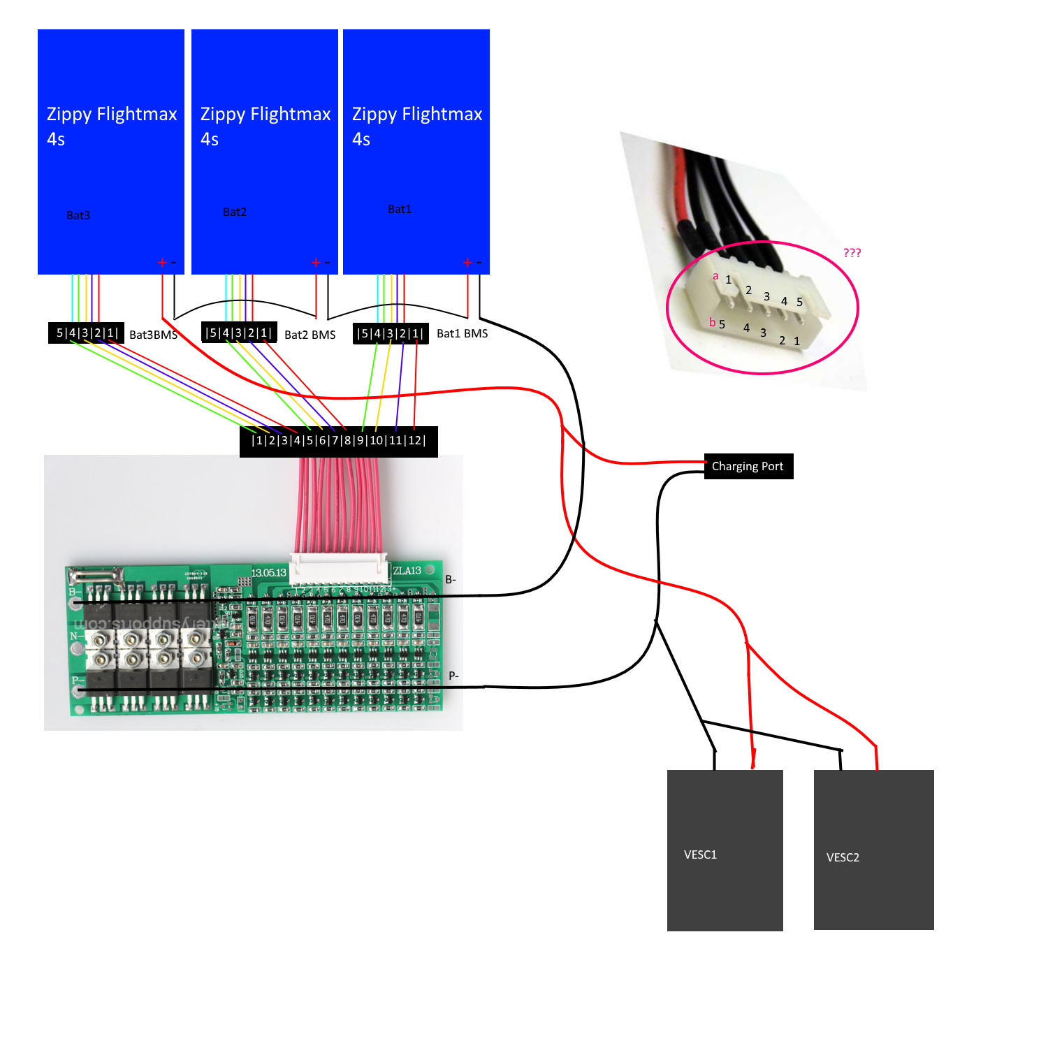
So I’ve ordered a Supower 12S 60A. I have 3x 4s LiPos in this config. My idea here is to somehow bypass the bms while riding, so I want to just use it for charging. I appologise for the horrible diagram, I hope it is understandable. I was not sure which pin is 1 and which is 5 etc. for the JST connector. Is it variant A or B on the right side? My JST cables look like the one in the picture with the red cable on one side. Thanks for having a quick look over this and letting me know if it’s right.
3 Likes
This doesn’t look right, if you want to bypass it, then minus (-) from the battery should be connected directly to VESC as well. Unless B- and P- are in direct contact which I don’t think they are because then charging through BMS would not make sense…
Yeah, this diagram is without the BMS bypass discharge. I just wasn’t sure how to wire exactly, so I left it out. How about the Balance cable?

So variant B.
If you turn the BMS like in this image, from the left to right start with first + balance lead and proceed up to second to last one.
Don’t bypass a 60A BMS. You lose one of the most important features: individual cell voltage over-discharge protection. This is especially critical with lipos. Often a few of the cells will have significantly more voltage sag, and it only gets worse over time. You will be unknowingly wrecking havoc on your batteries
So for example, if you drop to 46.2V under load, you might think all your cells are at 3.85V. But this is the ideal case, and generally is not true at all, especially with lipos. Some cells might be at 3.95V, while one cell might actually have drifted down to 3.2V or lower. Release the load and they all go back to the same voltage. So you think your pack is “balanced”. But its not balanced under load
3 Likes
Thanks for those insights, I did not know that.
Right On! @jmasta
Also if you bypass, you would not have short circuit protection which can save your entire system if a short occurs.
This happened to me on one of my builds when a had a short at the charge port. The bms instantly shut the whole system down and nothing was damaged.
Besides you don’t need to bypass anyway with a 60a bms.
2 Likes
I plan on upgrading to dual motors within the coming weeks, and I have hit 50A with my single motor on startup, do you think when I upgrade it will cause the BMS to become overloaded?
I have this same exact bms wired with discharge enabled 
How do you know your hitting 50a and do you mean 50a motor current?
Yes I mean 50a motor current, from a slow start with a tiny uphill. I have the hm-10 bluetooth module installed with the VESC monitor app
Battery current and motor current are not the same. Battery current is normally less and they are both controlled by the Vesc anyway.
Ohhh okay so the current monitored by the app is the current drawn from the battery?
I’m not familiar with the app you’re using I wouldn’t fully trust those Bluetooth apps anyway. I have the Metr module and app and it doesn’t even display voltage correctly. I have tested battery current with an inline watt meter. Running dual motors going up a fairly steep hill the total current draw on the battery was only 18 amps With 12s voltage
1 Like
ah apologies, the app I am using is the one from Ackmaniac’s thread. The VESC Monitor
Oh alright that is good to hear, thanks for your input 
I’m currently running an 80a Bestech bms. Dual motors with Vescs set at 80a motor max and 50-60a battery max for each Vesc. Even when riding hard up hills I’m having no issues.
1 Like
Sweet. Can’t wait to upgrade mine for that extra punch at the beginning and better brakes
So I’ve figured out the balance wires wiring and created the connector. Now I just have 2 more questions: Is the vedder switch wired correctly according to this diagram?
How do I solder this switch: https://www.aliexpress.com/item/High-Quality-1-PC-New-Waterproof-16mm-12V-Latching-Push-Button-Power-Switch-Black-Metal-Blue/32767204345.html to the Vedder antispark to make the LED light up? Am I right in assuming I need a voltage converter or can it be done otherwise somehow? If possible, that would be great, as I could save some space…
@capfirepants I have never wired a BMS but I guess the the schematic is correct, otherwise you’d have to switch your board on for charging.
To make the LED light up while your board is switched on you need to use an additional resistor, it says 1,9k on the picture but this will most likely be too bright, use a value between around 4k and 6k instead.