@chaka : Ok I got it. For some reason I thought the nunchucky was a different brand of wireless nunchuck. But in your opinion is it realy hard to solder the dongle directly to the VESC? Do you solder the thin dongle wires that are already there ?
Yeah I like that idea. Test with plugs and then solder.
I wouldn’t run a skateboard with plugs or adapters because it’s just one more point of failure added to the mix. None of this stuff is designed to withstand the amount of shock and vibration of skateboarding.
Thanks for confirming. That is what it looks like to me as well. @jacobbloy’s comment confused me since he mentioned the 5v
so @jacobbloy must have made resoldered a new connector for 4.10 ? If he was reusing his old 6-pin theres no way that position in that photo would work right ?
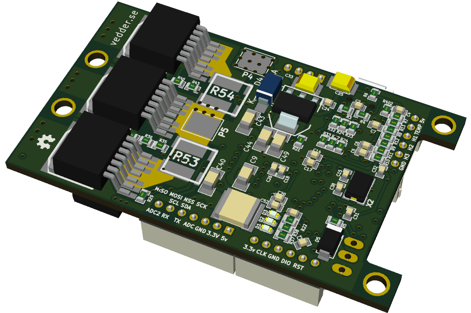
*edit I just took a look at some of the older diagrams and the schematic on Vedders site and it does look like you are right, the pinouts are the same with the addition of the ADC2
crap i just noticed my Nyko Kama receiver doesn’t match the one from the guide either… have any of you guys seen this variant of the nyko kama receiver?
I actually have the little converter pcb thing in this post:
So that labelled the pins for me before I cut the wires to the head.
Heres a random diagram from google images that seems to be consistent with the convert pcb thing:
Keep in mind this view is looking at it from the front. When you look at it from the back ( the part will you will cut the wires ) the left and right will be opposite.
Well the pinout image is not the nyko kama, thats just the standard wiimote pinout i found on a site. I don’t know what device that is. Or are you referring to my actual photos with me holding the pcb ?
Anyway I just finished soldering it to the connector. I don’t have the vescs yet so can’t test it out, hopefully my soldering wasn’t too bad lol.
Can you post a dia gram with the 7 pin connecter as im sure being able to see it will cuase less confusion because its not much mention and i would hate to fry my vesc cuase of wrong wiring @jacobbloy if you understand can you please post pic im checking diagrams jus wanna be sure of rite connection who woula thought one pin could mean so much i have no ifea what a adc2 is scares the hell outta me lol


