The Bronco | LHB Deck | Turnigy SK3 6374 192kv | VESC | Nunchuck | 10S 5Ah LiPo Battery | Psychotiller Enclosure

Hey everyone,

I began getting all the parts together for this build back in November when I first started lurking this forum. Originally just threw everything together on an old skateboard deck that I planned to cut into a cut into a cruiser deck shape but that was kind of terrifying to ride so I ended up getting a @longhairedboy deck that I am very happy with now. It’s not complete and I don’t think it really ever will be since there’s a ton of (probably unnecessary) things/features I still want to add.

My roommates gave it the name “The Bronco” since it has bucked all three of them off from cutouts causing them to fall at kind of scary speeds and the board has some nice battle scars to show for it. I’ve learned to just accelerate slowly (since a cutout then is harder to recover from) and when it reaches a safe cruising speed I’ll just brace for the inevitable drop out and let off the throttle so it’s not that hard to deal with. Eventually I’ll probably just get an enertion controller but I still kind of want to make one myself so we’ll see. Number 1 on my to do list.

The part list:

  • LHB deck sporting the natural wood look
  • Turnigy SK3 6374 192kv Brushless Outrunner Motor
  • @chaka VESC
  • (2) Turnigy 5000mAh 5S 20C Lipo Packs
  • Vedder Anti Spark Switch
  • Wii Nunchuck Controller
  • @psychotiller V2 Enclosure
  • @torqueboards Mount/Pulleys/Belt 16T/36T
  • Caliber II Trucks
  • 83mm ABEC 11 75a Flywheels
  • Bones Reds bearings

I absolutely love the look of the wooden deck with the green and orange Abec 11 wheels

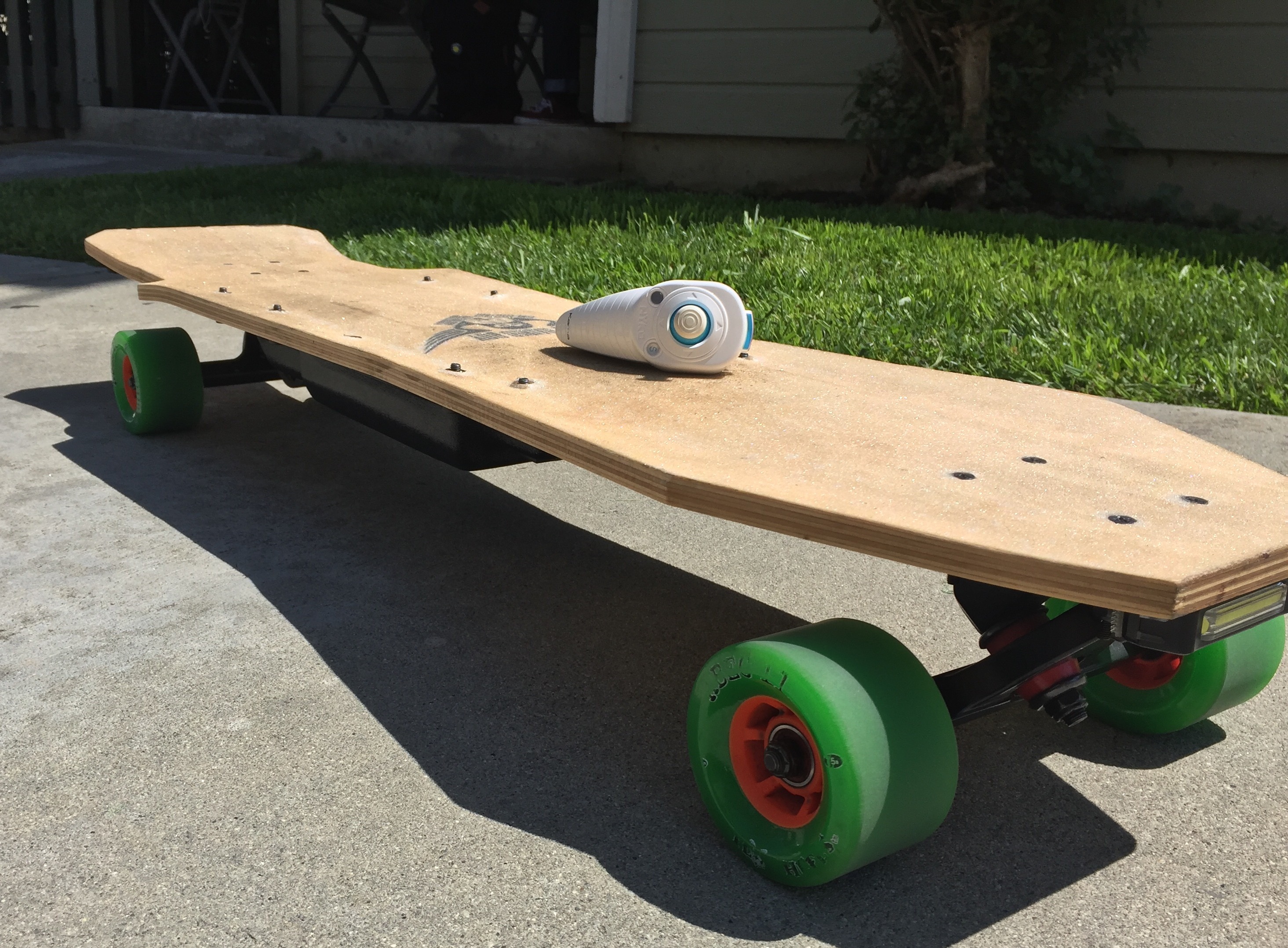
Still need to buy some shorter screws for the enclosure since you can seem them poking through the top a little bit here

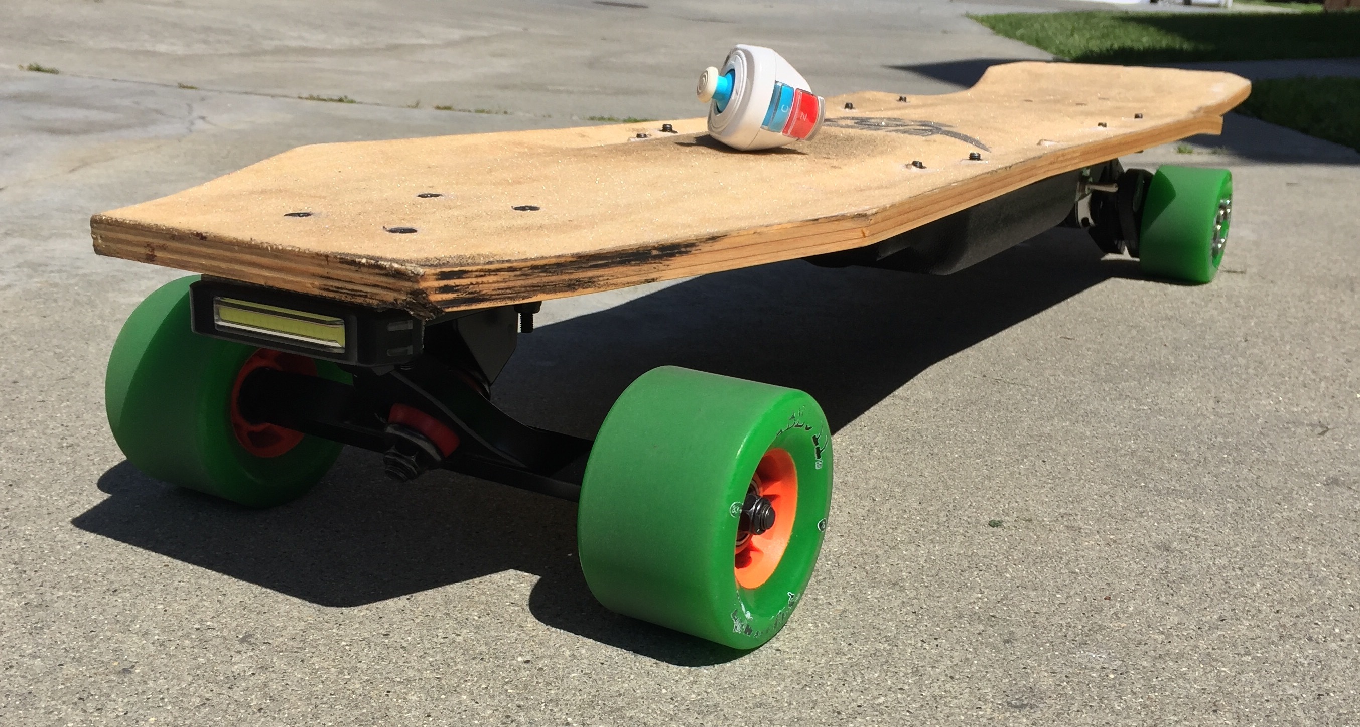
Headlight and tailight held on with the 3M dual lock faster tape velcro thingys so I can easily take it off when it needs to be charged.

Some nice scuff marks from tires/curbs when the board went rogue

Surprisingly you can’t really even feel the long screws peeping through when actually riding. The board has a kind of concave up shape on top that levels it out a little bit I guess. I’ll probably put dark grip to cover the screws but I also don’t want to cover LHBs beautiful logo

Before I made a foam gasket for the enclosure there was a lot of vibration and a couple screws rattled out but it doesn’t really need all 10 anyway

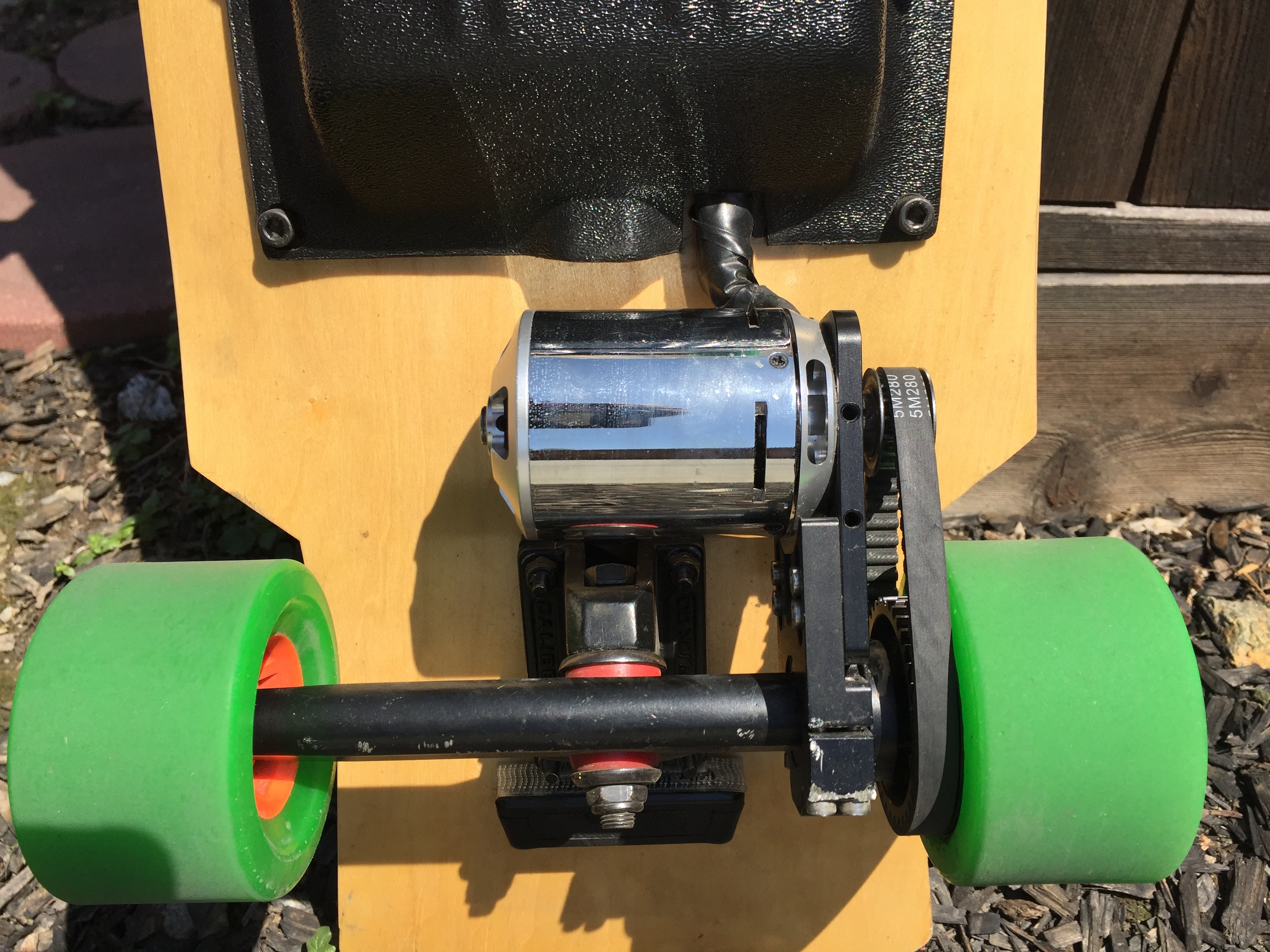
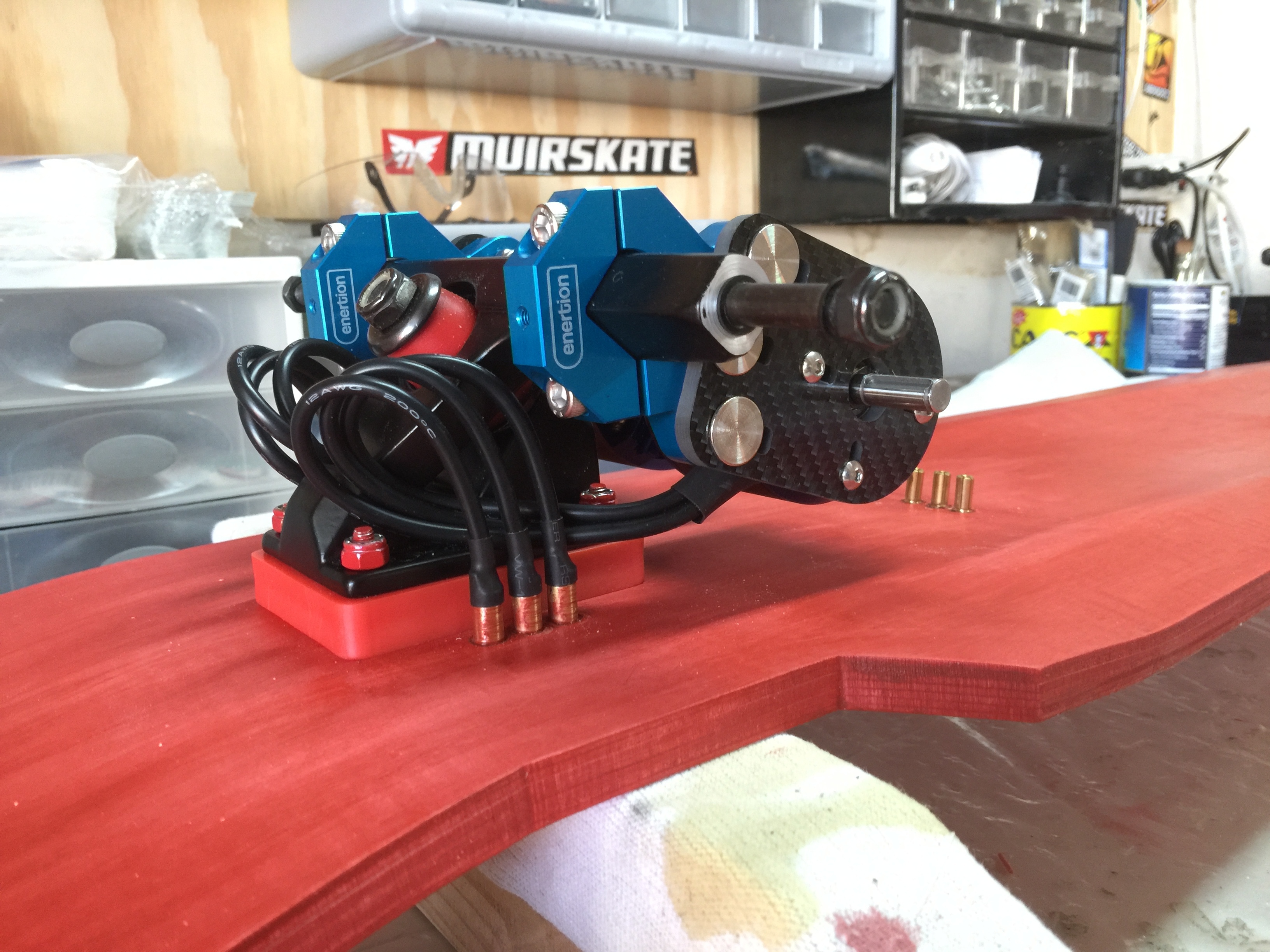
9mm belt with 16T/36T geating ratio. Not a big fan of the 9mm belt. Torqueboards mentioned a few weeks or months ago that he was going to start selling a 15mm set up which I still have my fingers crossed for. I spent a few hours in different CAD programs (zero experience in) trying to modify the open source pulley from the enertion website to 15mm but just got frustrated and gave up. If anyone knows how to get hold of a 15mm wheel pulley it would be geatly appreciated (already have the 15mm motor pulley from Torque)! If not I’ll probably just grab one of enertions new injection mold 12mm pulleys.

Also, I cut a separate slot for the motor wires because every time I tried to push them in the designated slot, the motor would eventually hit the wires and cut through the insulation. It’s also just more convenient with the VESC right there.

VESC/Spark Switch/Batteries held down with the 3M latching stuff. I originally thought the dropouts were a motor connection issue since there was one loose motor bullet connector falling out when I took the case off one time. So I decided to solder the motor wires directly to the VESC (the red you can see is just shrink tube not bullet connectors). I didn’t realize the VESC has an LED that lights when it is receiving a signal from the controller, which would have told me right away from a couple tests that it is actually the controllers fault for the dropouts. The nunchuck receiver is soldered directly to the VESC (not just connected with the JST connectors or whatever those are called) and hot glued over to ensure that they were staying put. I also thought that maybe the receiver near the motor could be a connection issue with the motor being a big magnet and all. But the dongle is actually way up at the front in front of the battery not seen in this picture, held down with the 3M latching tape and of course, wires soldered and covered in hot snot to keep them in place. Really feel like I did everything I could to ensure a perfect connection to the VESC but it just wasn’t meant to be.

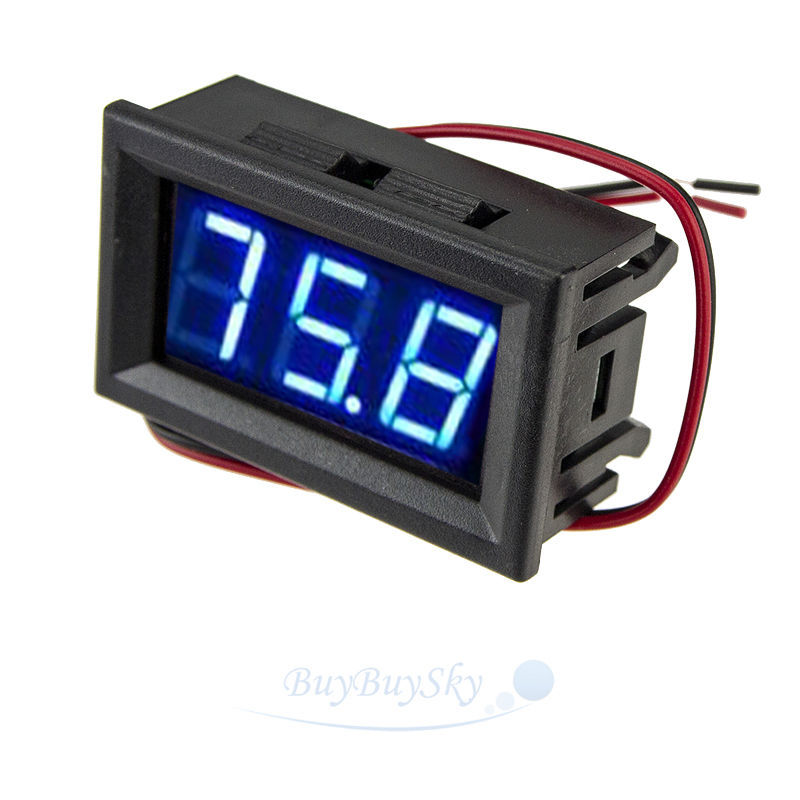
I put 2 voltmeters in the enclosure because the first time I put the board together, one battery stayed around 19V while the other dropped to 12V and puffed. Turns out it was just a dud battery and the new ones stay within 0.1V but it’s also just kind of a cool look in my opinion. Still need to add a switch to turn them off though since I have them connected to the battery balance cables and they stay on even when I cut power to the VESC

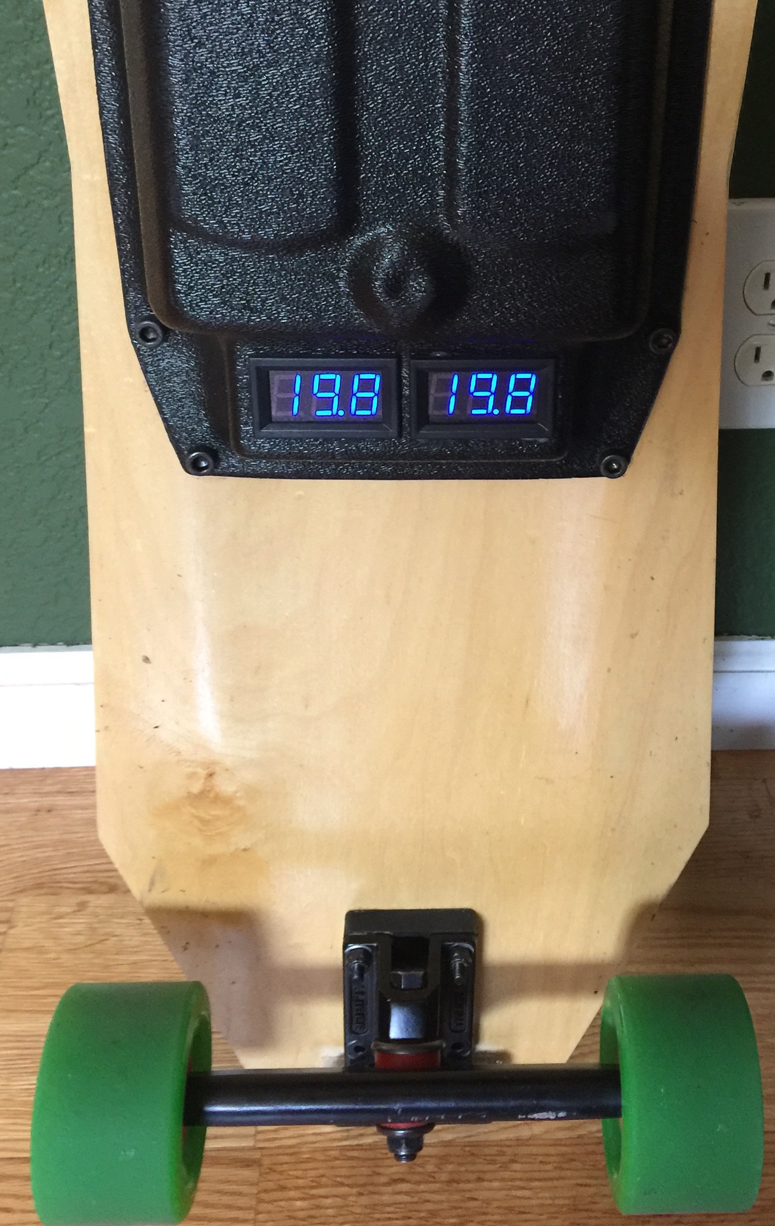
They’re a lot bigger than I expected but they still ended up fitting nicely in the enclosure

It’s been a fun and frustrating project and I’m excited for how it will be looking/working in the next few months

8 Likes

Its wonderful to see her in the wild. Simon stole my tomato but i’m coming back to read your entire post.

Great build @SpartanScrub ! I recently learned that those voltage meters that connect to the balance leads only draw power from one cell in your battery, so if you leave them in for too long they will through the cells out of balance. If you don’t have a way to unplug them or turn them off, you might want to remove them and rely on VESC’s low voltage cutoffs.

1 Like

Yea I figured leaving them on would eventually cause problems somehow. Had them connected for about a week so far though and each time I’ve gone to charge the batteries the biggest difference in cells was only 0.02V, so not too bad. The leads are only connected to the red and black wires of the balance cable so I’m not sure how that would drain only one cell though.

Actually bought a couple push button switches to turn them off and they just came in but they’re momentary switches. Oops. I think I can turn them both on/off with a single DPST switch but I’m kind of scared I’ll wire it wrong and short them haha so maybe I’ll just be safe and get 2 separate SPST switches

1 Like

@SpartanScrub it sounds like you’re getting a lot of cutouts! Are you exceeding voltage thresholds on VESC, or is your nunchuck dropping out? I switched to a gt2b controller after many failed attempts to make the nunchuck more reliable, very happy with that choice! If you haven’t already, check your voltage thresholds in BLDC Tool and adjust them for your battery; you might be able to eliminate the cutouts. GL!

Yup lots of cutouts! I plan on going the gt2b route just not sure which one yet.

Do you mean the voltage limits on the motor configuration section? I have it set to 42V max, 10V min, 36V cutoff start, 35V end. I usually only ride when the batteries are between 36.5-40V.

I’m 90% sure it’s the nunchuck. I held it at full throttle for looking at the VESC to see when the LED went out and sure enough, maybe once every minute or so, the light would go out and the motor would stop (well not stop, but slow down and coast) even though I was still pushing up on the nunchuck for full throttle. The drop is for random times too. I’d say anywhere from a 0.2 seconds to almost 2 full seconds. Then the light will come back on and it goes back to full throttle.

Looks great man! super clean- I loved the LHB deck that I built for a friend as well:

The one thing I’d change is the orientation of your motor wires- having them face the enclosure makes them get pulled every time you turn. If you loop them from the back (I put them through the riser) it takes away all the stress because the are at the pivot point of the truck.

Just some food for though, as over time the stress can cause an unwanted short :smile:

2 Likes

Interesting. I never even realized that. The motor wires kept getting grinded down till the copper was exposed and I thought it was just the angle of the wires going into the enclosure and the vibration but this makes a lot more sense! Thanks for the tip!

And I definitely saw when you posted that board! So clean. Even before I had the powertrain on this board it was so fun to just cruise on. It’s also pretty fun telling people how it’s a custom hand made deck!

2 Likes

Ok i finally read your whole post. Its always awesome to see somebody using one of my decks in a build. I haven’t sold very many of them, so seeing one pop up now and then feels good.

I love the look of the voltage meters, but yeah, @treenutter is right. You might want some different ones that just wire into the mains directly. You could still have two of them, and maybe even find some that look just like that but don’t use the balance leads. You pretty much always want your volt meters on the mains between the power switch and the ESC so that it turns off when the ESC does and it doesn’t just drain one cell.

Also, the phase wires. Like @cmatson said, you should point the phase wires toward the back of the deck and then sort of loop them back under so that they flow back into the box against the bottom of the deck. This will greatly reduce stress on the leads and allow them to flex as the truck turns. Here’s an example on the raptor mono:

and a close up of one of my Scarlet builds has them doing the same thing, except they plug in next to the truck instead of going into a box because of my wire channels:

3 Likes

I pushed around on my prototypes for a few months before i ever put power on it. They’re hella stable and make for some really fucking fast downhill boards because of it, which is why they make great esk8 decks. I really enjoy making them and i’m glad to hear that you’re passing the word around. :slight_smile:

I took a few cues from some of the more interesting downhill boards and tried to work them into my design, which is how i came up with that rather interesting flat-top w-cave. That profile serves multiple purposes: It stiffens a 7 ply deck to the point of seeming more like an 8 or 9 ply (still a little bit of flex, but damn, its a 40" deck), provides a shape that cradles your arches and gives you a nice crevice to put the pad of your rear foot, and also gives you a bit more room in the box by raising the ceiling, so to speak.

It’s actually just a regular DC voltmeter, not specifically for lipos. So it just has the the positive and negative leads, not the full balance connector. I just made a connector to connect it to the balance cables so it’d be easy to take the case off.

I feel like I could just add a switch to each voltmeter like this

They’re basically attached to the battery mains already but I don’t see how I could attach both to the anti spark switch. I think I could only get one total voltage through that, but not the individual voltages of each battery.

But yea, can’t say enough great things about this deck. Thanks again!

2 Likes

How did you connect your turnigy motor to your VESC? Turnigy motor has the banana plug.

Female banana connectors. They hold in place fine