Wel then as I said u wil nod need 2 open the lid of ur longboard

Yeah i know. It must be a closed circuit.
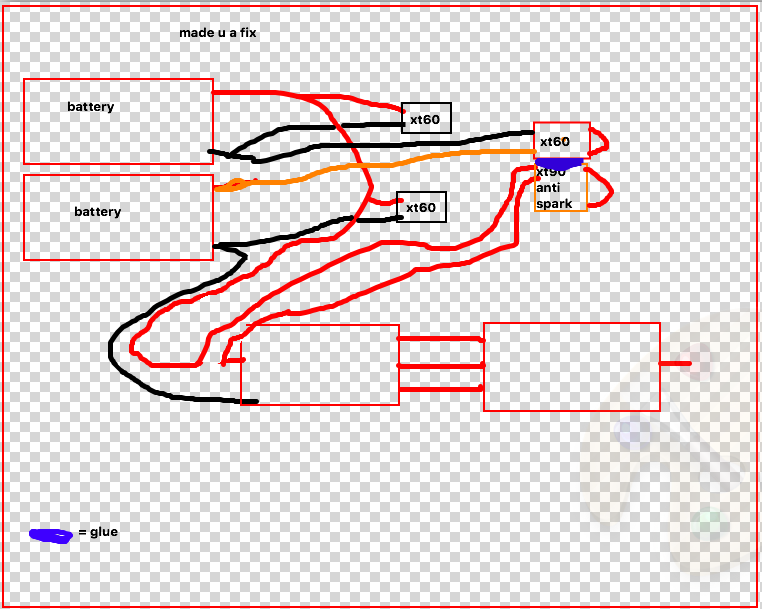
But when you attach a parallel board or parallel wiring for charging you have a closed circuit ![]()
 If you connect the wiring in the right green circle you have on both wires energy. When the XT90s is detached you still have a circuit from the parallel wiring (other green circle)
That is not true however. What causes heat is the current not the voltage (which is why powerlines usually operate in kV range). So if you use your switch at higher currents than its rating, you are introducing additional losses and resistance into your circuit. Basically up to a point where the metal in your switch acts like a fuse and blows/melts.
Yes this can be done. That is how I have my packs wired. For this you need to use a parallel adapter on the balance lead one end will go to the charging port and the other to the voltage meter but on this one you will need to install a on/off switch on the negative wire so you can turn the meter off.
Have you had any problems with over heating of the switch like Maxie said?
When you charge, you remove the XT60 key to stop the ESC circuit. That is the one the positive lead goes through before hitting the ESC. You also remove the XT90 key.
Indeed! My initial question was what wiring can be used to charge in parallel and discharge in series by only plugging in/out one key. The current solution needs to keys.
Well that is an easy fix  just make one plug ot ouf two but it is not very convenient to de-/attach
wel if u glue the if ther in i weel be a okay fit hahahahahahahhahahahah:joy:
I liked this idea, but @Kaly s idea with the switch to switch between parallel and series circuits is in my mind more convenient. The only thing is with this talk of the switch not being able to handle the current. Any comments on that?
@Maxid That is true about the current (Amps) being the source of heat. But you need real worl assessment on this.
Don’t miss interpret this  but, I recommend you buy a switch open it up, take the contact elements make an evaluation of the cross section and determine the heat that will be generated on the system with the parameters we use on eSk8 applications and then we can resume this conversation
The switch works flawlessly for almost a year now. The contact elements inside the switch are capable of handling the current with not problem.
I have wired 5 boards with this switch and no issues at all.
The issue @Maxid bring up is correct but that is if you only judge by the rated current on the switch. In my case this is a $ 4.50 switch so I opened and got the cross-section dimension and did the calculations for the amount of heat that was going to be generate with the load of my application and the switch have almost a safety factor of 2.
1 Like
do u have any 6000 wat switch u can recomend???
A 6kW mechanical switch is not feasible for our purposes. It would be way too big. That’s why we build electrical switches from mosfets in parallel to achieve the necessary current rating
Here’s a 4kW changeover switch. It’s massive. I bought one with the hopes of making it smaller. Not possible. It’s probably 3" in diameter and 4" long.
That will. E a super big device. In thing we need to have clear is that if you use 10S or 12S battery you are not going to be pulling that many amps even in extreme situation even here I’m just pulling 50A on 12S, measure with a watt meter.
To add on to your statement… The power dissipated is proportional to the current SQUARED. Therefore the heat generated goes up exponentially with the current. That’s why it’s not as a simple as saying the switch is good for 2.5kW.
In real world testing the switch seems to work. But for how long? You are really pushing it to its limits. But they are cheap, so maybe you are alright with that risk. I was going to go this same path and then just went with a 12S BMS. So much simpler and safer for not much cost increase
P.S. @Kaly, I really do like your design! So don’t take this the wrong way. I’m just being a conservative engineer.
2 Likes
There is always a option for BMS Like this one http://www.batterysupports.com/lion-lipo-nbsp-36v-nbsp-10s-c-32_41.html
If you really want to use the parallel/series switch, here’s a way to double the capacity of your switch.
Use a 4PDT switch (4 pole, double throw) instead of DPDT. Then split each of your leads in parallel across two poles. This effectively cuts your current in half!
https://www.amazon.com/4PDT-Heavy-Duty-Toggle-Switch/dp/B001TJ6O9M