Part nine: Elecrtonics in my Ninja e-board
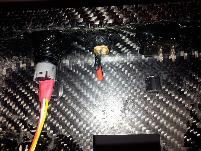
First thing I’ve done was gluing antispark switch, LED switch and charging port using black ninja style hot glue:
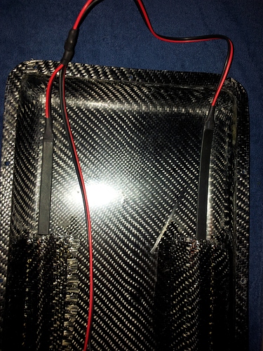
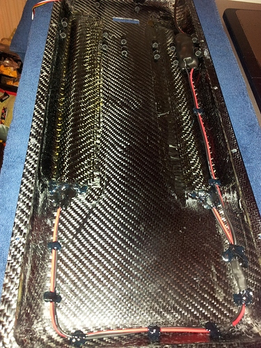
Next was sliding LED strips into LED sliders and close end with hot glue so that LED strips stay in place and also for water protection. I also glued LED wires to enclosurre, in other words made a cable managment. So no cable mess, no noise from cable wiggling in enclosure from riding vibrations:
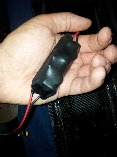
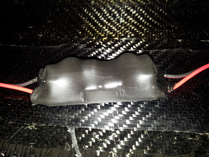
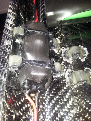
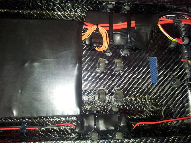
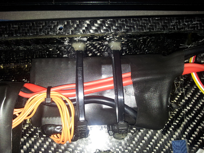
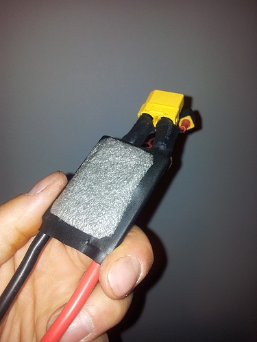
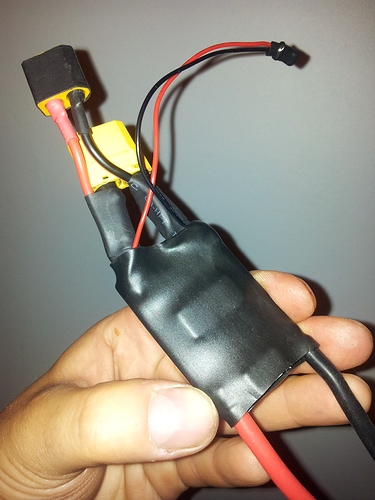
Since my deck and enclosure are made of CF and it is highly conductive material, all electronics should be isolated with heat shrink. I have different sizes of heavy duty heatshrinks, so heatshrinking has begun. First I heatshrinked voltage converter for LED strips and then attached it with zip ties to electronic holders wich I made earlier:
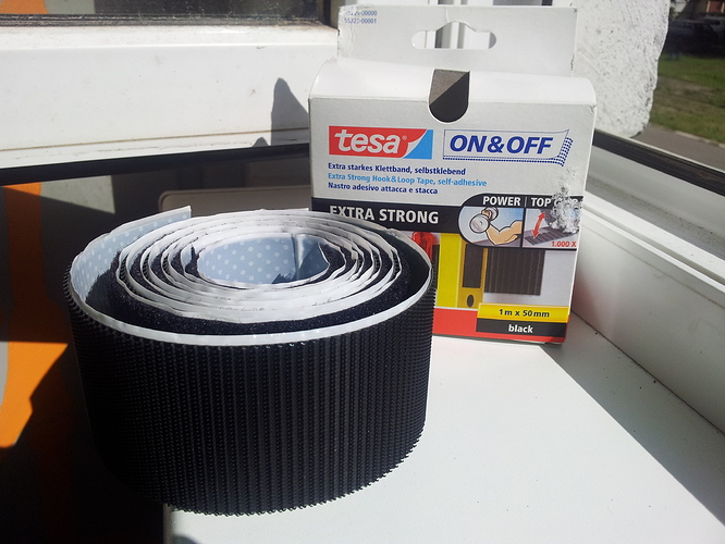
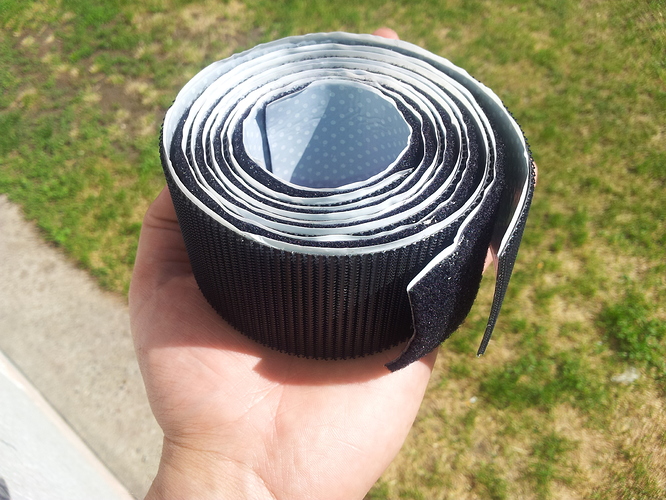
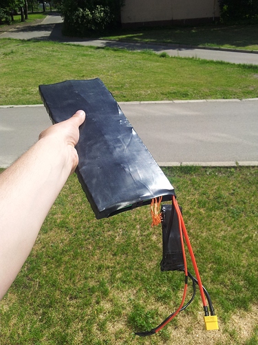
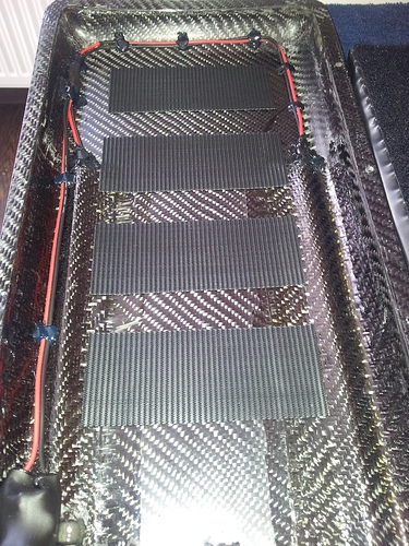
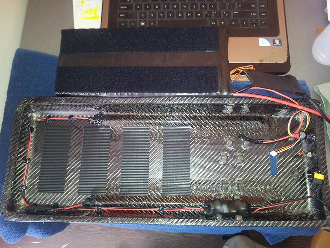
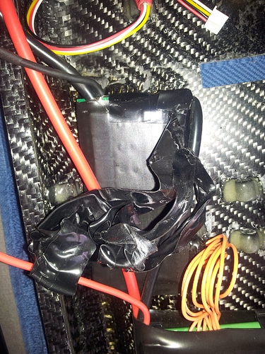
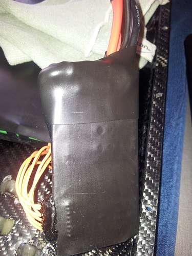
Next is battery attaching to enclosure using industrial strenght heavy duty velcro, like this:
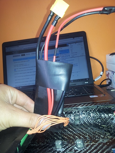
Here’s battery just before applying velcro to it:
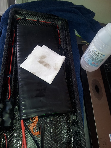
Before gluing velcro to enclosure and battery I cleaned surface with isopropyl alcohol to get rid of all dirt and fats what can riun your work:
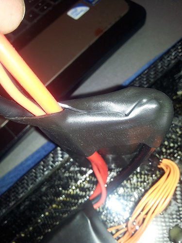
Then I added velcro on the battery and done the same thing with cleaning and adding velcro to the enclosure:
With this velcro battery stays very secure in place. I had no need to take battery off enclosure, but I’ve tried to lift about 1/4 of battery and it was super hard. Other electronics except bluetooth module and receiver, I decieded to not attach with this velcro, because, voltage converter and BMS are placed in the corners of enclosure. There are no smooth surface to attach to, there are curvature of enclosure, so big gab without contact. VESC has mosfets wich are higher level as whole PCB surface, so also not really smooth surface + they getting hot. Antispark also has no really smooth surface. Thats why I invented those zip tie holders for electronics. There are also two options how to attach electronics using zip ties with my electronic holders:
-
Place your electric device in place, and zip tie that whole tie is at the top of your device. In other words whole loop of zip tie is on top and device is under. That way device will be pressed to enclosure, so full contact with the base.
-
Place your device in place, and zip tie that, zip tie is going around your electric device. So one piece is on top, other at the bottom. In other words device is in the middle of the loop of zip tie. That way device is actually not touching enclosure too much. I used this type for VESC because I thought it would be better for cooling.
Next thing in my case was making better isolation of BMS, because one side of my BMS was taped with electric tape. And I don’t want electric tape in my build, because tape is nasty bich  From the heat and time glue from tape is leaking away, making sticky and nasty goo.
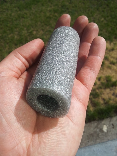
For absorbing vibrations I am using this stuff, you can buy it in any home depot:
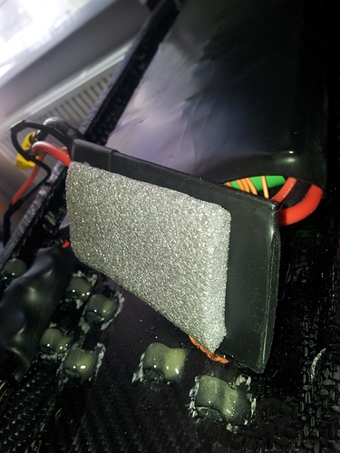
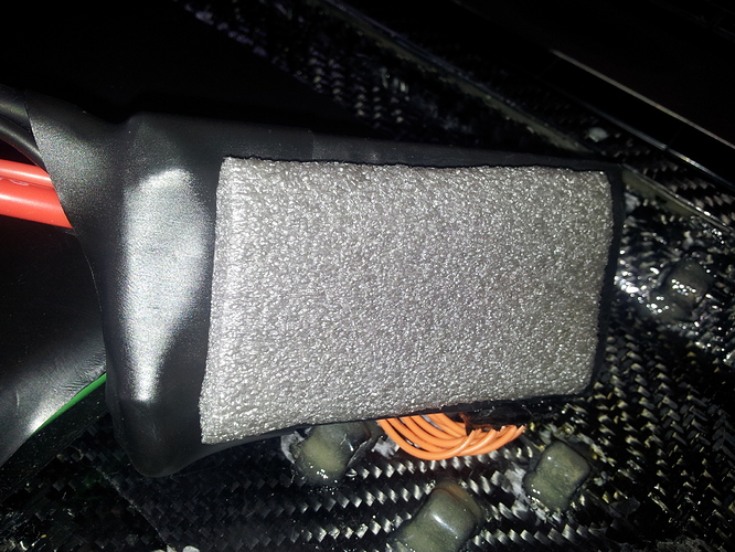
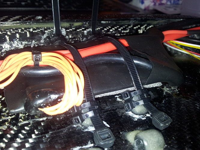
So next thing was to place BMS in place and zip tie it + adding foam under for absorbing vibrations. Same foam I used for volt converter too. I used it for VESC too, but it really not helping with heat issues:
Next I added volt meter, I decided to glue it with universal transparent silicon, so it would be not so hard get it off when needed and silicon is great for sealing, so more water resist. I scratched a bit surface of volt meter contact points and surface of enclosure for better silicon grip:
I added heat shrink of course and after gluing with silicon I added ninja black hot glue, mostly keep the heat shrink in place and extra strenght and water resistance:
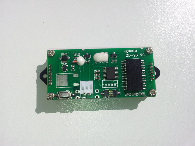
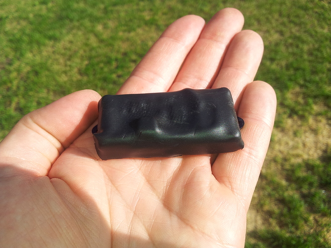
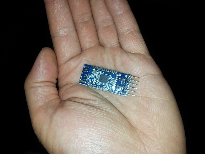
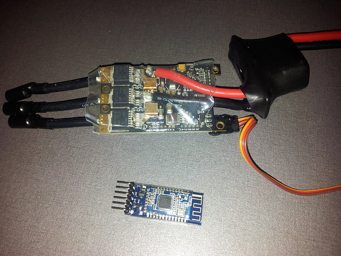
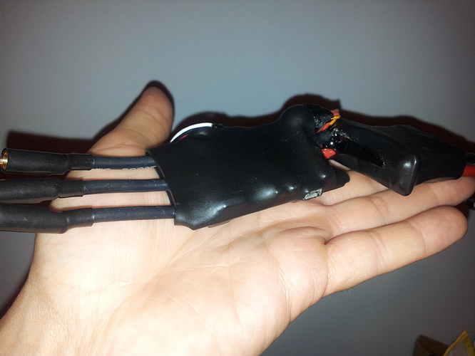
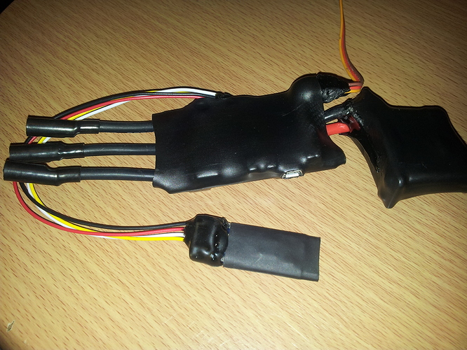
Now its time for soldering bluetooth module to the VESC, so some photo porn:
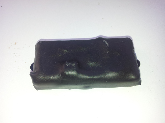
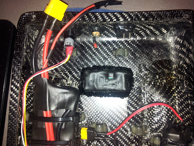
Heat waping whole bluetooth module was mistake, because, antenna should be open, free from everything for better signal. Also on VESC mosfets should be out for better cooling, I should cut small squeres where mosfets are.
Next was attaching VESC with zip ties. Bluetooth module and receiver I attached with superman strenght velcro on the sides of enclosure. All cables was manage by hot glue:
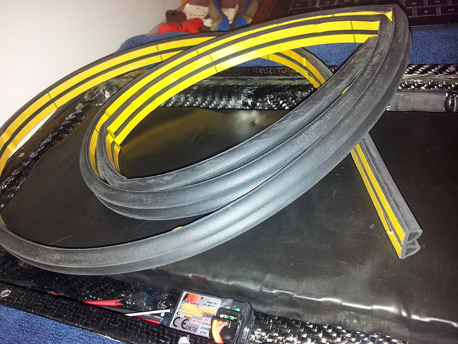
For sealing enclosure I used this:
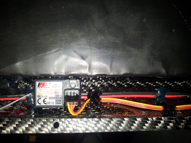
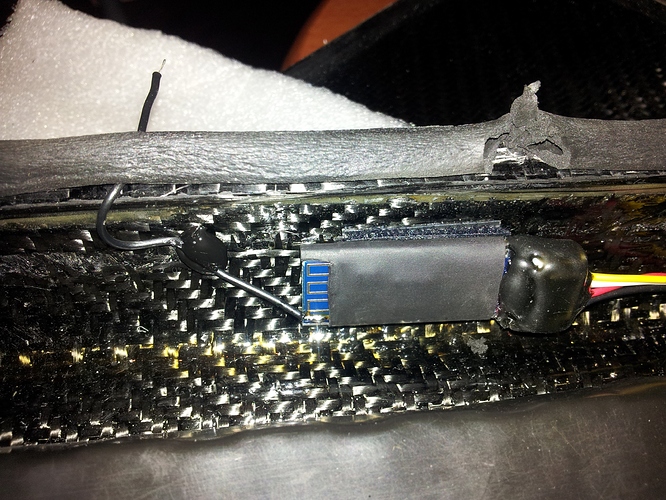
But when I tested my board I had issues with CF wich was blocking radio signal and bluetooth signal too! Rrrr…, crap…  I sorted out receiver signal issues by placing antenna out from enclosure:
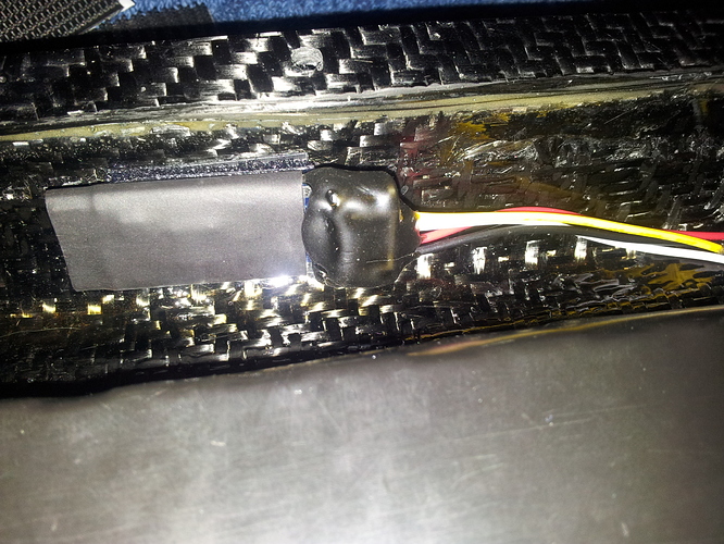
I’ve tried the same thing with bluetooth module, but it was total fail. It was only working when whole module is outside enclosure, it was working even through two concrete walls with metal construction armature in it, about 8m away. But not working through 4 layers or CF!!  :
:
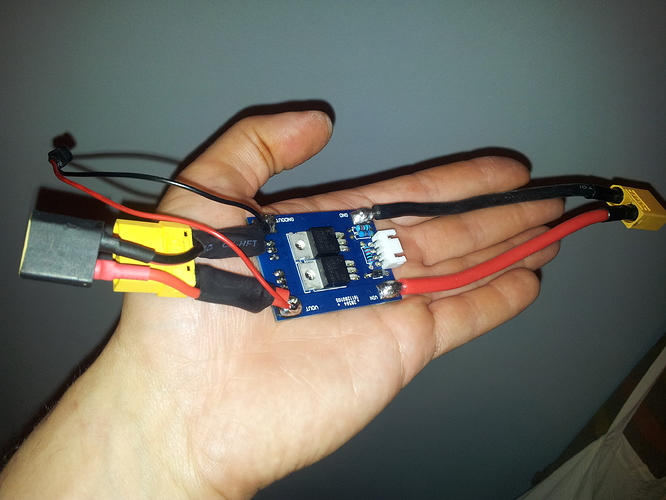
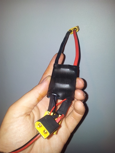
Time solder antispark and heat wraping it:
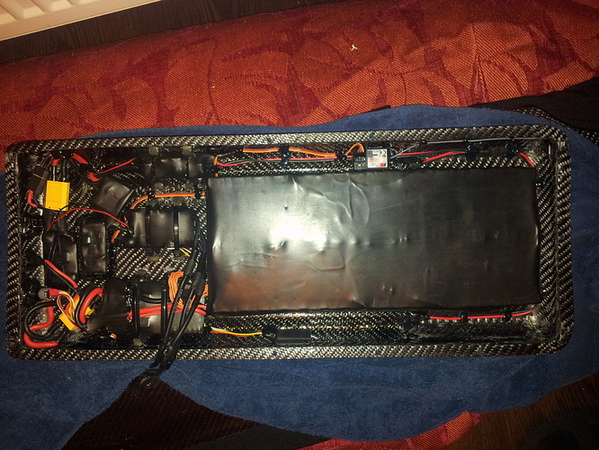
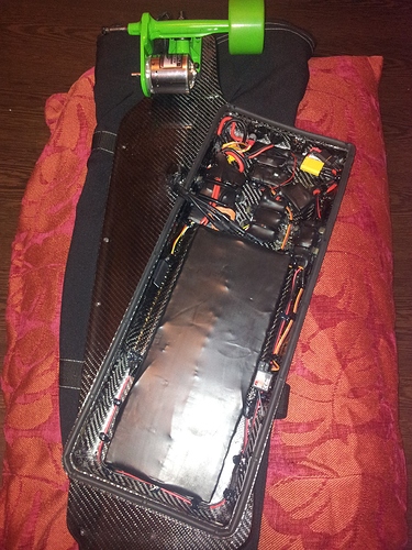
After placing antispark device with zip ties, all electronics together look like that:
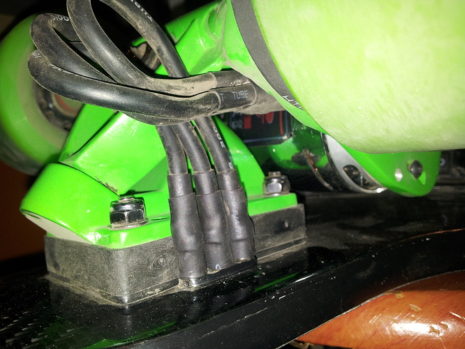
All bullet connectors what goes to VESC I had exta supported with heat shrink after they are connected, because they can get short, all over is CF and they are close together. I’ve also put extra heat shrink on here, because one bullet connector was completely disconnecting while I was riding from vibration, I was lucky that it didn’t short. Because all connectors on deck was naked with no heat shrink, it easely could short. Of course main reason was that one mail connector on motor was a bit pressed so it was not tight in female connector on the deck. I used small screw driver to open bit male connector wider, after that it fit tight in place. Anyway I put a heat shrink for extra safety!!  :
:
So for now that is it, wait for bluetooth solution, how it looks completed, maybe some ride videos too…
Peace 























 I am inspired by the work. I will soon make my own FG enclosure. Your log and many pictures are helpful


