Are you talking about soldering the battery tabs on directly? That sounds like something you would need a custom PCB design for (the pad locations would be to match up to your battery exactly). The pads here are designed for wires to be soldered on before connecting the battery. Moving them far apart to allow for safe soldering of live wires would require a complete redesign. I can space them out even more, but i still don’t think it’s a good idea to solder things live.
1 Like
We have a couple drones that run 6s. Solder wont stick to the pcb so running the iron across the spacing make the solder wick back into the solder on the pads. Im pretty sure Raphael addressed the arching thing and spaced them out enough for no arch to occur.
You are right. It is called Battman.xls . I searched for BOM 
This here does have a lot of power?! https://www.amazon.com/gp/product/B01GFVI6R6/ref=pd_sbs_23_4?ie=UTF8&pd_rd_i=B01GFVI6R6&pd_rd_r=GPZNM1HGSVPB8RH87F1T&pd_rd_w=kg1KU&pd_rd_wg=KtrTJ&psc=1&refRID=GPZNM1HGSVPB8RH87F1T
1 Like
this thing will never ever be able to charge at 18A. It says 900W but check the German amazon website and you will find a review of a guy telling exactly this. Also you would still need an actual power supply supplying the DC voltage.
I have a adjustable 32-40V 15A power supply for my drok coming on the slow boat from China right now
There will be losses (quite large ones) so with a 15A supply you will not be able to actually charge with 15A.
What kind of boards are you guys riding anyway that you could ever need such a charging current?
6 parallel charging at 1.75 equals 10.5 And some battery’s can be fast charged at 2A
1 Like
Who actually uses 6P batteries and needs to charge them as quickly as possible? Also fast charge usually means more than 4A per cell not just 2A. You can safely charge at 1C although slower is always better to get healthier cells for longer.
Assuming 10S6P that would result in something like 540Wh up to 650Wh. That gives you more than 50km in range - who needs to honestly fast charge after a 50km ride?
1 Like
So my 6s4p hg2 are 4a max charge so your saying I can actually use this bms to charge at 16a because of the 4p ?
I don’t know the max charge current of @raphaelchang s BMS but in general you can. Parallel cells “add” the individual max charge current to give you the actual max current for the pack. However as I said you should always charge as slow as possible to keep them healthy for longer.
Yea I understand as seen a 5a charger but wasn’t sure as max was 4a and my bms can only handle 5a but I do like these bms and esc just hope they are a sensible price.
Make it the Batman tune by default “na na na na na na na na, na na na na na na na na”
3 Likes
Let me try to explain the charging circuit with a little more detail. The circuit is a boost converter with a current limit on the input (as most boost converters do) of 6A. By conservation of power, the product of input voltage and input current must equal the product of output voltage and output current (minus efficiency losses). For example, if you supply 24V and want to charge a 48V battery, 24V*6A = 144W, so you are limited to 144W/48V = 3A at the output. Therefore, the closer your input voltage is to your desired output voltage, the closer to 6A you will be able to charge at.
There is also the option of bypassing the boost converter and charging the battery directly with the power supply, the traditional method. To explain this, this is the schematic of the charging circuit. C+ is the input supply and CHG+ is the output to the battery. The boost controller IC is on the left and a DAC is on the right.
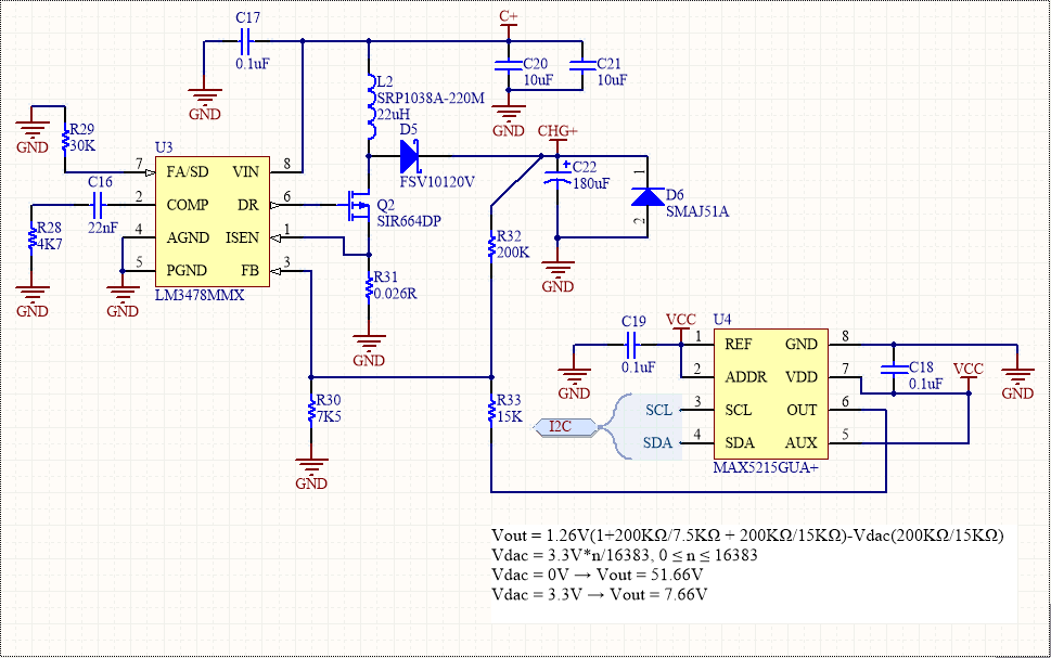
Using the DAC, the circuit is able to adjust the output voltage of the boost converter by injecting a voltage into the feedback pin of the IC. Normally, the desired voltage would be higher than the input, so the controller would be switching the MOSFET to boost the voltage up. However, when the bypass option is selected in the configuration, the firmware will make the DAC force the boost converter to output a very low voltage, lower than the supply, which the converter cannot do. Therefore, it keeps the MOSFET off, and the circuit simply becomes C+ -> inductor -> diode -> CHG+. This simple current path allows for a higher current because the controller isn’t involved. The charge current will be the current rating of the power supply, but the ratings of the inductor and diode mean that the current should not exceed 8-10A.
Currently there is a limitation in the boost controller IC that limits the input to 42V, so any battery pack that is more than this will require the use of the boost converter. Using the boost converter means that you can have CC/CV charging with any input supply because the voltage can be controlled accurately, whereas if you bypass the circuit, you can only have CV charging if your power supply is exactly the CV voltage of the pack. If you plug in a higher voltage supply, the BMS will simply cut off the charging (with another MOSFET) when the battery pack reaches its max voltage, so you will only have CC charging.
Long explanation, but I hope this clears things up a bit for those who are curious.
8 Likes
The diode will dissipate quite a bit of power. at about 10 amps this could easily be close to 8W (0.8V diode drop). I have the same limitations in my BMS design. There is just no easy and cost effective was of solving this.
2 Likes
Here’s a bit of suspense for you guys:

16 Likes
Now you’re just teasing 
1 Like
Wow, it looks ridiculously small !! Great job !!
Wires seem to be soldered very close. At least for my soldering skills…
Cell balancing:

13 Likes
Sign me up!!!
Boom!
1 Like
in Exhibit A we have a spec sheet for Samsung 30Qs. on page 3/17, it states max charging current at 4 Amps and standard charging current at 1.5 Amps. Then look at page 8/17 and 9/17. With 4 Amps charging it reduces to 72-74% capacity with 250-300 cycles.
in Exhibit B we have a 20 Amp 12S charger available for sale and shipment now.
With a 12s6p pack 20 Amps would spread over 6 batteries width so: 3.3 Amps per a cell.
You would hurt the life of the battery somewhat with these aggressive charging currents, however it is well within safety spec. Still can be nice as an option to fill those batteries 5 times faster than a 4A charger.
Anyways my point is I’m starting to prefer the idea of small capacity but rapid charge ability, and there are batteries out there which welcome such behavior albeit at an expense of capacity. This would make for a small quick commute board, which lives by the charger constantly.
I’m looking forward to purchasing this in the future. Do you have a sort of time-frame? I searched the entire post for words like “date” and “when” but nothing applicable came up. If you don’t have a timeline that’s also fair. Some times food has to be prepared accordingly, so I understand. Like TeleRando… sign me up!