I’m not sure, never done it, but they do stainless steel and similar materials I believe.
Also steel and aluminum (along with other plastic materials)
1 Like
You will pay big bucks for a metal shapeways part. I would recommend what @torqueboards said, it would be hard to adjust it, unless done before mounting.
Agreed it will still be expensive, but if you REALLY wanted to, that’s probably the best way. Just wanted to put it out there as another option.
1 Like
To adjust it is simple, set in the screws and move the pice till your belt tension is to your standards. Tighten one side of the screws (this will stop it from sliding) then tighten the other side by either taking it off the truck or having the truck already off the board and just resting, that way you can flip the truck over and tighten the other side
1 Like
I posted my mount files. @Raf 's mount is actually based on mine. I dont know how to put a cover image on thingiverse, and well I dont feel like messing with it. So here you go: http://www.thingiverse.com/thing:1726523
I made this out of aluminum and you can see pics of it on my build thread
1 Like
looks alot like the enertion opensoure mount…and just as complicated to make.
the arms/sides of the motor plate would be too thin for printing. and the slots in the y axis makes it even worse.
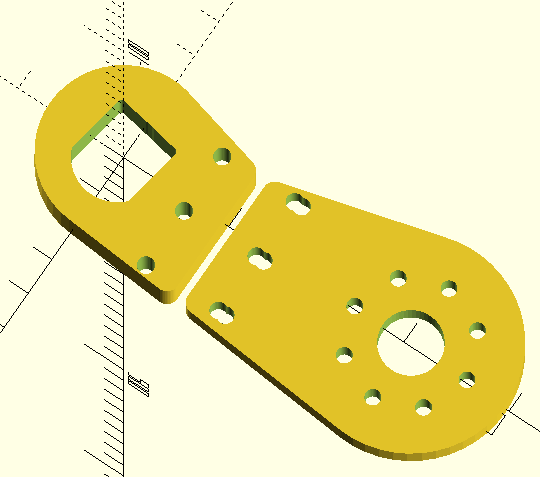
i just started one yesterday, inspired by psychostiller, tbv4, enertion…
its a 2 piece, will cuts in the same plane. still need to split the clamp, and slot the motor plate for tensioning. kiss ( keep it stupid simple).
2 Likes
I agree with KISS! Hahah I am probably going to make a second version using the flaws of this one and strengthening them in the V2
nice renders, however there design might have a weak spot, is this alum? what is the thickness of these areas?

2 Likes
yeah aluminium and 5mm x 6mm
the thickness needs to be at least 10mm, otherwise the alum will snap…
2 Likes
I don’t understand why you designed it this way in the first place. It is completely “overengineered” to the point where the design is complicated to manufacture and does not even have any benefit compared to simpler solutions (look @torqueboards mount for example). To me it seems like you wanted to design something that looks cool without thinking of making a better mount than what is already available. You obviously have good design and render skills - you should try to design something simpler but with the same functionality.
To get an idea you could for example think of the following: What is the benefit of having the screws for belt tension on the top and bottom? What is the curve actually doing (structural integrity - why not just an edge)? Why single motor mount holes instead of slots?
Looking forward to your next mount - will be stellar! 
Where do you get this 10mm figure from? I totally agree that looks way too weak, just wondering if there is some standard or something you are basing that on?
the “clamp” walls look a bit thin. The caliber hole should be ~1.8cm wide - according to the drawing that would leave less than half of this as material on your mount for the clamp screw. That is probably not enough.

lots of real world testing of various materials over the last 3 years
2 Likes
Sweet, so would you say anything load bearing made of aluminium thinner than 10mm by 10mm is a bit suspect?
He just said thickness! One dimension should be 10mm - the other can be less. Look at the plate thickness on torqueboards mount - that is ~6mm if I remember correctly.
I know, I guess that’s just what I’m trying to figure out. I’m new to working with aluminium so not really sure how much to trust it. sorry, probably asking all the wrong questions! Just trying to brain pick 
6mm 6061 will be fine. 10mm isn’t needed. The only reason why I had motor mounts that have broken in the past were due to making it too complicated and having stress points by adding too many bolt holes where they shouldn’t be which affects the strength and durability of the motor mount. But I’ve also upgraded my motor mounts to 7075 which make it much stronger.
3 Likes
Thanks for the feedback. Before making the mount i didn’t understand how cmc milling worked and didn’t realise that this design would be too complicated. I originally had 2 piece mount (the motor part and the clamp) but then realised i wouldn’t be able to adjust the belt tension but didn’t want to make it the same as the other designs so i put it on the side not realising it would be a weak point.
Ive sent the design to get 3d printed in cheap plastic to see how it fits together with paris trucks and my motor. Using this i will make a new design with a simpler layout but with the same needed features and maybe more unique features if i can think of some, whilst keeping a simple design.
This has been good as i can read the feedback and make improvements.
Thank you!
2 Likes