Maybe try to set max input higher than 42v… I got a similar problem here.
Put the max voltage at around 57V if you are using a space cell pro, also I may suggest to drop the MAX ERPM to 70 000 to prevent damage on the drv.
1 Like
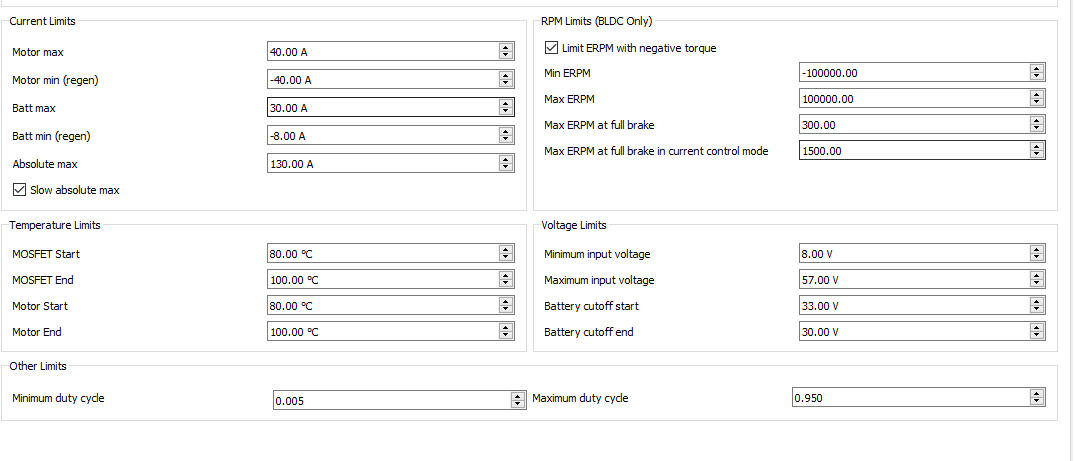
If you’re running dual motors, your current limits are too high. Keep in mind that values should be halved since you’re running dual setup. I’d make motor max 40-50 per vesc and adjust as needed. motor regen should be at 40ish or you will be braking pretty hard. Battery max is a bit low and should be higher at about 30amps per VESC. Your SCP4 supports 80A continuous, but you want to try to be below that. Battery regen is too high and it should be -8A per VESC for safe charging.
1 Like
Wow thanks guys. Glad I asked.
See below for new config. Any last things before I stress test it?
Thanks.
Looks good, though your low voltage cut off end is a bit low. You can keep it at that for more range, but make sure you get to a charger asap when you feel it kicking in.
This gives you an idea of how a voltage meter reads % to voltage.

1 Like
My advice is similar to his, though he was speaking about the SCP3 not 4
Got it Jinra,
Looks like 36 at 10s would be safer. I’ll update that.
I do 33v cut off start and 32v cut off end personally. You’re voltage will sag while riding so if you start the cut off too high you might trip it when riding with high current draw like up hills.
I did not say that your advice where not good, but, there is not so much difference between the SCP3 and SPC4, because by using the same 10S bms, they are in fact limited to the same continuous current. The major difference between the two are in term of the capacity and range they provide.
Also, you may want to use a lower Batt Min, at around -15A so it will provide a better braking solution.
Actually the SCP4 outputs 80A continuous vs 60A on the SCP3 due to the extra parallel cell. This also affects charging current so -8A battery min (dual vesc) is the safe spot for these cells. There is more capacity on the SCP4, but charging/discharging is also affected.
I have -8A on my dual VESCs with 45A motor regen and have no problem braking hard.
Yes you are right, my mistake there is a difference between the SPC3 and SPC4, but the continuous current is still not rated for 80Amp, it is the peak current at 80amp.
Pack rated to peak output of 80AMP, However incorporates a 40A Fuse for protection, this is ample for use on electric skateboards. This pack is for motors of 2400W or less (Including the 6372)
http://www.enertionboards.com/electric-skateboard-parts/space-cell-pro4-electric-skateboard-battery/
peak is actually higher than 80A, but you’re right it wont support continuous 80A, but should work for bursts. I’ve been trying to find a small fuse that’s rated higher than 40A to replace the stock one, but have had no luck finding one in this size. I may just swap out the fuse holder for a larger one that supports 80A.
But, be aware I think there BMS is only rated for 60AMP. So if you’re going over the bms limits you will probably burn the bms internal fuses (if there one, but with these Chinese (for now…) product you never know), or the BMS.
True, I’m not too concerned though as I’ll replace the BMS as well. Though with my current limits and constant uphill riding, I’ve never tripped the 40A fuse yet. Esk8 probably doesn’t pull that many continuous amps at 10s.
Ok, I put everything together and all seems to be in working order. However the motors only spin together intermittently. I think my JST connector is faulty. When I jiggle the wire the motors spin together, otherwise I only get one. I bought a JST connector from Ollin board co, but it broke immediately. I’m currently using one from a local hobby shop. Anybody have a good recommendation for a quality JST that will last?
I wouldn’t recommend connecting it like this for this reason. Mine would move ever so slightly and cut out my motor. I gave up on various solutions and settled on soldering the connection in place.
Interesting, I didn’t know that was an option. Do you have any pictures?
You can take the wires out of the plastic JST housing and solder directly to the pins. Make sure to push all the way down.
Got it. What is the purpose of the ferrite ring?