I’ve seen some of these motor mounts broke in 2 pieces in some threads, maybe not the best choice.
I’ve bought this one which is also not top notch quality but at least looks more stable to me. But check if it can hold your motor and suits your trucks.
Thats a great call out, I hadnt yet thought about clearances between the motors. Im not sure exactly how to measure the length of the trucks; they are either ~186mm or ~254mm depending on where you measure from:
Just eyballing it, you’re right that there isnt going to be enough room to mount the motors symmetrically as you have. I do have quite a bit of ground clearance though, so Im thinking Ill either stagger them or mount them on opposite sides of the truck. Does that sound reasonable to you?
What is the difference between your 6374s and the 6364s I linked? Reading the product descriptions, it seems like the 6374s can handle 10S - 12S, where the 6364s can only handle 10S. Is that the only difference?
Thanks for the recommendation! Ill give these a consideration. In first glance I like the fact that the ones you have a 19mm bracket hole for the trucks vs the 18mm hole in the ones I have; my trucks are slightly over 18mm, which means Ill need to shave/file them down slightly to fit my current brackets. Ill have to do that anyway though, because the Paris trucks are pretty heavily chamfered from the axle to the mount meaning Ill need to clear some of the metal out anyway. I also like that the ones you linked come with a mounting bracket for the wheel gear on the opposite side of the wheel vs the ones I have do not have this. The final drive ratio with 12/36T vs 16/48T would be just fine as well.
I dont like the price though… plus the fact that I already bought these.
in the ebay post, product photos, that 3m designation indicates pitch depth.
a search will get you your answer:
i’d recommend against this. unless you have a drill press for perfect angles, just get abec core wheels so things just fit together without having to modify things by hand.
Just wait until you start breaking parts and frying chips… I thought I was going to stop at 1100$ for my single build. Then the second motor, then fried a drv, etc. etc. fuck this hobby.
You’ll have to let me know how you like those wheels… They’re really quite appealing now that they’re made with 8mm axles. I wonder if it will be as soft as pneumatics.
So, after a long ordeal with the manufacturer, I swapped the wheels out for regular 10" pneumatics. The 8" rubber wheels were nice enough on visual inspection, but I never got to use them for a number of reasons and moved on.
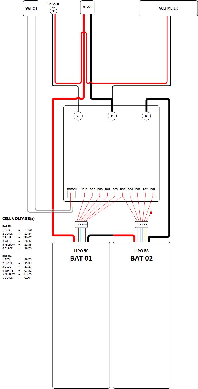
However, I cant figure out how to connect the battery to the charger? I see the connectors are different, but Im totally unsure how to wire them up together. Ive searched and found info on building a loop key for charging, which I think I can do, but that is only part of the problem. Any help?
Also, Ive read somewhere that I shouldn’t program the VESC with the 10S battery, and need something with less amps… is that right? I bought two of the Torque VESCs which according to the product description come pre-booted and dont need the initial startup amp protections, but what about using the 10S battery for programming as well?
Thanks! Im sure the connector is for the charge port, but Im not sure what you mean by “solder one into the XT60 connector” - is there a diagram somewhere that describes this?
Update: Ive got the electronics sorted out and the VESC connected to the BLDC tool. It was a PITA figuring out how to get the BLDC tool to work in Windows, and I made a small post on how to do it in the FAQ section here: link
I can make the motors move, but they are moving a bit erratically. It seems like there isnt enough power getting to the motors, as the board will move without me standing on it but if I stand on it there isnt enough torque to move my weight.
 plus the fact that I already bought these.