There you go! Thanks @lowGuido
ok so now that I’m out of bed, I’ll get a bit more detailed for you. here is how it works. … pictures say 1000 words so…

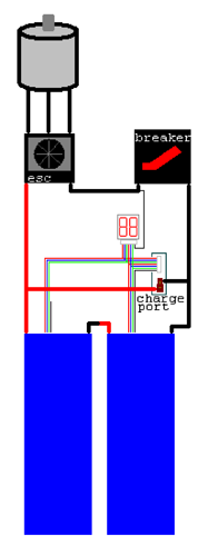
Left is what you have. Right is what you need.
the important thing to realize here is that the black wire on the left most pack is actually the same as the red wire on the right most pack. which is also the same as the thick red wire in the middle. so by connecting the small balance lead to that board (I can’t see how that board is wired I can only assume logic) if you have your left one and your right one mixed up, the black wire is basically just shorting straight across the positive and negative of one of your series batteries. make sense?
in saying that if you were to plug you 2 balance leads into the opposite ports, that board you have will still work assuming its not itself fried.
edit: in fact now that I have had time to look at your images in detail I can clearly see that you have plugged the negative balance lead into the positive side of the board. The damage doesn’t look too bad so you can probably still use that board. just make sure you connect the leads the correct way. (why would they even sell something so confusing)
TLDR: guessing which balance lead is the more positive and most negative is annoying and potentially dangerous. best solution is the right side of my diagram above with one 8S balance lead.
1 Like
im trying to make this as easy to understand as possible… sorry if I’m waffling on… so heres where you went wrong. (again I still don’t understand why they sell a product that’s so easy to confuse)


Thanks @lowGuido! Amazing detail and amazingly helpful. Last night I also contacted HobbyKing since this is the board that they actually recommended I get for this weirdo battery. They recommended that I cut off the two 4s connectors from the 8s battery and wire up a single 8s connector. I can’t imagine why in the world it wouldn’t come that way but I instead just initiated a refund process and I’m just going to simplify my life and get a different set of batteries with normal charging leads. That being said, your diagram still comes in handy for wiring the new batteries up together to balance charge down the road.
Thanks again!
I also connected my balance cables in series and had a massive spark. My batteries were connected in series. Did you have your batties connect in series?
I then speedster the batteries and connected them in series which much more caution and I didn’t get a spark. I then connected the batteries in series and had no spark.
I have not tested this while charging or using a BMS. However I am sure it’s just the process that the barriers must be separate at first then connect the balance cables and then connect the batteries in series.
Anyone else had a similar experience?
As it turned out, I had the wrong balance board for what I was trying to do and since went a different direction with different batteries. I was attempting to connect them in parallel at the time though. Lipo’s do spark when you connect them though, especially at the higher S’s
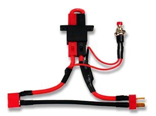
@siggs3000 @Paul There are a few ways to avoid the spark when connecting Lipos; I use a battery arming switch that has a small, temporary resistor. Kinda like this thing below. If the spark is just the normal “connection spark,” the danger is that it will wear out or melt your connectors. This thread is about something more complicated, but I thought I’d note that it is possible to mitigate the connection spark.
There are also xt90 antispark plugs, which are effective but giant:

@sl33py is working on builds of Vedder’s antispark switch
Actually that’s true. I received my new vesc yesterday from @chaka and it has those diesel XT90 connectors on it with heavy duty 10 gauge wire and it doesn’t spark at all when I plug it in. Super nice.
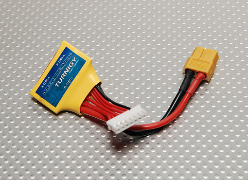
Hello guys! Sorry for posting in an old thread but my problem perfectly fits in here. So I plan a build with 2 3s lipo packs wired in series. I bought this serial charging harness - http://www.hobbyking.com/hobbyking/store/__10993__Twin_pack_charge_lead_2_x_3S_6S_w_XT60.html, which has XT60 plug for charging while my imax b6 charger’s cable has a dean plug. today I removed the xt60 from the harness and soldered the dean connector to be able to connect the charger’s cable and the harness. Then I thought I’d try to connect the batteries (though there were not used yet, completely new) and the harness together - to check the soldering quality - to see if voltage would be there with a voltmeter. So I connected to batteries in series (as on photo), then I plugged the 1st balance lead into the harness’ port - all was good, when i connected the 2nd batteries balance lead - there was a pretty good spark, you can see the damage of one of the pins. could this have damaged the lipo? I measured the voltage afterwards - was fine.
I am a real newbie. Can someone tell me what did I do wrong? I tried to read the forums and this thread and if i understood well i should cut out the black wire of one of the balancing leads according to @lowGuido’s beautiful diagram. But I feel confused because everyone else seems to use my type of harness without any troubles. Thanks in advance.


heres what you do:
- Wire the batteries in series FIRST
- take your 2x 3s to 6s adapter and cut the black wire closest to the middle ( you will need to cut through the heat shrink)
- Now you should be able to run this safely if you plug in the lipo alarm/voltage reader and it shows 3s, switch the two connectors around.
If you do this in any other order expect to get a shit ton of sparks
1 Like
Hi, thanks a lot for your reply. I uploaded the photo of harness once more - I assume you refer to the thin black wire of the 6 pin balancing lead?
Does it matter where I cut this wire if I isolate the cut pieces well? I would also appreciate if you could shortly tell me why does this wire cause sparks? And I find it strange that this piece is sold as a plug-n-play product and there are some extra tweaks required… I also saw other people’s reviews on HK - they all seemed happy and noone mentioned cutting wires. 
Will I actually be fine charging through this harness - I mean using the dean plug I soldered? My plan was to do charge over the harness keeping batteries in the board however with a disconnected circuit (XT90s loop switch).
Thanks a lot!
Edit: BTW, you emphasized the order but you didn’t mention the right moment for connecting the batteries to the harness - should it always stay connected or it doesn’t matter when you connect them?
I should also mention I used this exact product, and charging was horrendously slow due to it being charged through balance leads. Instead, wire a xt60/Dean in parallel to the wires feeding to your ESC and plug in through that, it will provide a higher current.
- Yes I mean the thin wire on the 6 pin. You should isolate it.
- It shorts out, thus sparking.
- you should be fine charging with this harness, though like I said above its not as fast.
- Connect the batteries after all my steps
Thank you. so you recommend the following wiring (creation of @lowGuido):
I have couple of questions:
- I read somewhere that it’s not good to have long wires between the battery and esc, I guess it is not true?
- what is the min wire thickness I should stick to for charging wires - I read somewhere that AWG10 is min, is it?
Yes that diagram is great. 12 AWG is pushing it, 10AWG is perfect for our use. Wire length shouldn’t matter as long as it’s not 3+ ft. Though you want to try and keep it as short as possible. If you are using a VESC and FOC, keep it very very short!
You need to make sure that your most negative battery has its balance leads plugged into the negative side of the balance connector. Getting this wrong is what causes your short. (Spark)
Thanks for reply. Could you please clarify what means " the most negative battery" - the one with a negative terminal going to ESC?
And how do to determine which one of two balance slots is negative? Sorry for the “newbie” questions.
Will the method described by @link5505 - disconnecting the thin black wire of the harness balance lead will eliminate the necessity of watching for the most negative battery?
Thanks.
I don’t know what’s the AWG of the wire I have but it’s from the electric kettle - so handles 240v normally, and current of certainly 16A. That should do, right?

BTW: is it an idea if I use those wire endings / terminals (donnow how it’s called in English) to create parallel wire splittings for charging? I hope you get what I mean ? 
I would love to get a confirmation from someone. Thanks in advance.
that kettle wire will not do the job. buy some nice 12 AWG at a MINIMUM.
the “most negative battery” would be the one on the right of my diagram, the one that has the big negative wire to the ESC.
Hi, thanks for your advice, I did get some super thick wires - my colleagues use them for assembling the electric car chargers. AWG number isn’t there but the its a stranded copper wire with a total cross section of certainly more than 3mm.
Will the method described by @link5505 - disconnecting the thin black wire of the harness balance lead will eliminate the necessity of watching for the most negative battery? Thanks.