im in the process of wiring my esk8board and as i havent done much electric projects so far i would
really apreciate if someone could look at my wiring diagramm and tell me if everthing looks alright.
Before it get´s to the point where somebody questions my research, i´ve been looking around in this forum for months
and tried my best to understood everything as good as i can. But if you see some missunderstandings on my side pease
be gently as i really tried understand everthing correct.
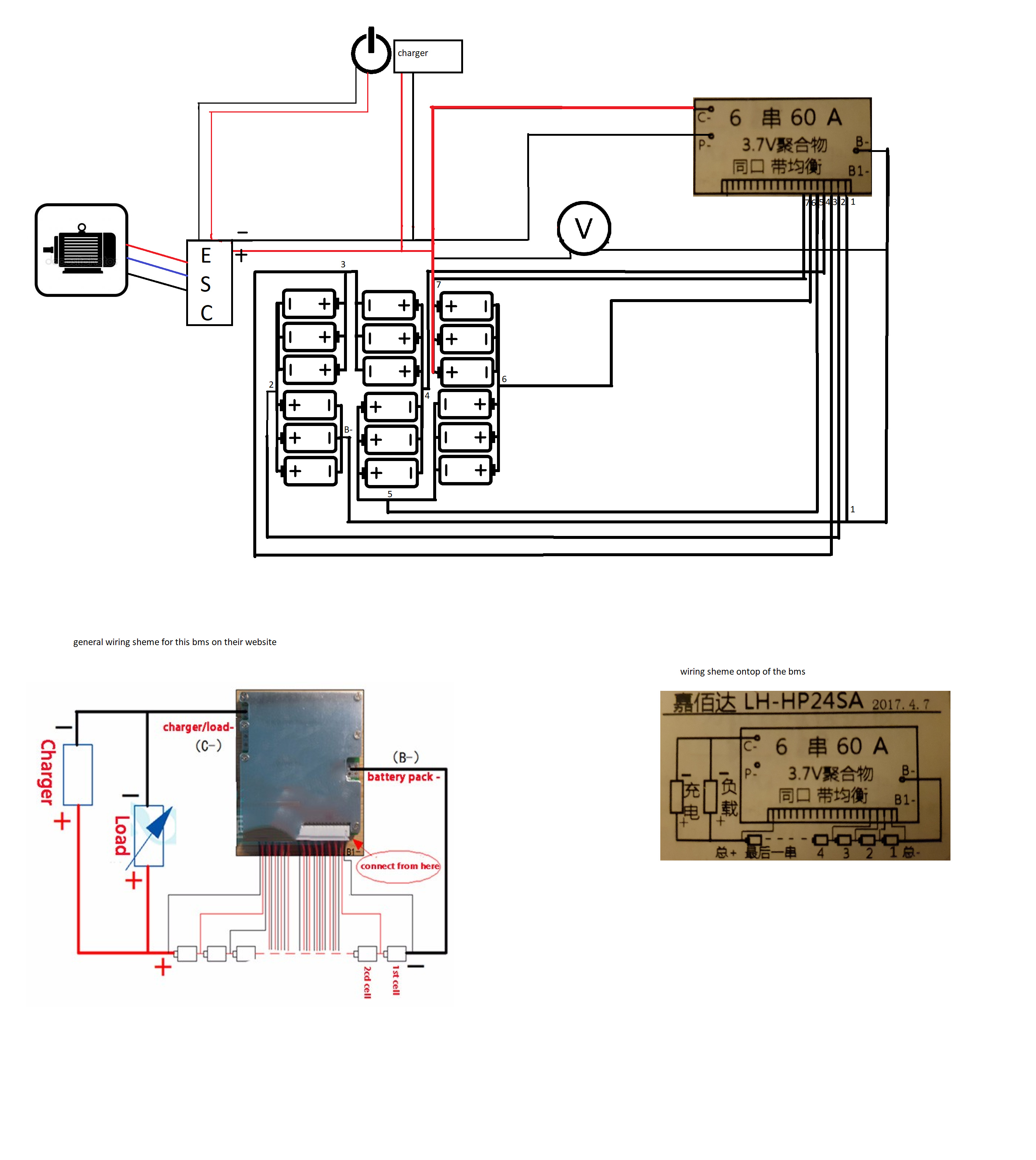
I tried to orientate on this thread but wanted to make it fit my physical setup to help myself getting not confused while wiring it, so if my diagram has some crosscuts of wires it´s just because the wires overlap there.
I have 3 things i dont understand.
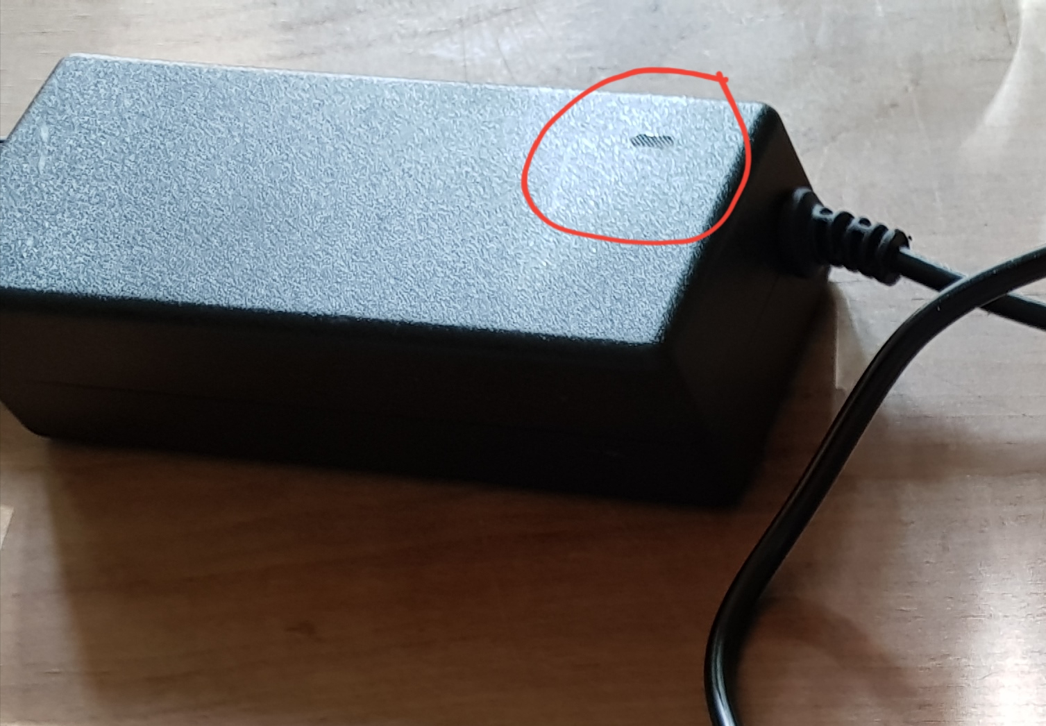
The given shemes on how to wire this bms don´t show the usage of P-, from what i saw P- has to
be connected to negative ESC. (i´ve put a red cicle on it to show what i mean)
What is the difference between “load” and “Charger” from the general sheme for this kind of bms ?
Should i use the switich of my ESC or wire one between the bms ?
I dont quite understand your diagram. firstly it looks like you have your esc and chargers positive and negative to the same wires connected?
in any case this bms switches the negative side so you need the following.
a thick wire (10awg maybe) from the battery negative to the bms b-
your esc, charger and battery positive all conected together, with a thick cable (10awg again) between esc and battery. and im not sure about the escs switch but i would add a loopkey in between.
the negative from charge to your bms c-
the negative from esc either to the bms p- (this would be your load) if you desire undervoltage and overcurrent protection from the bms, or directly to the battery negative. (10awg again here)
I think that is all?
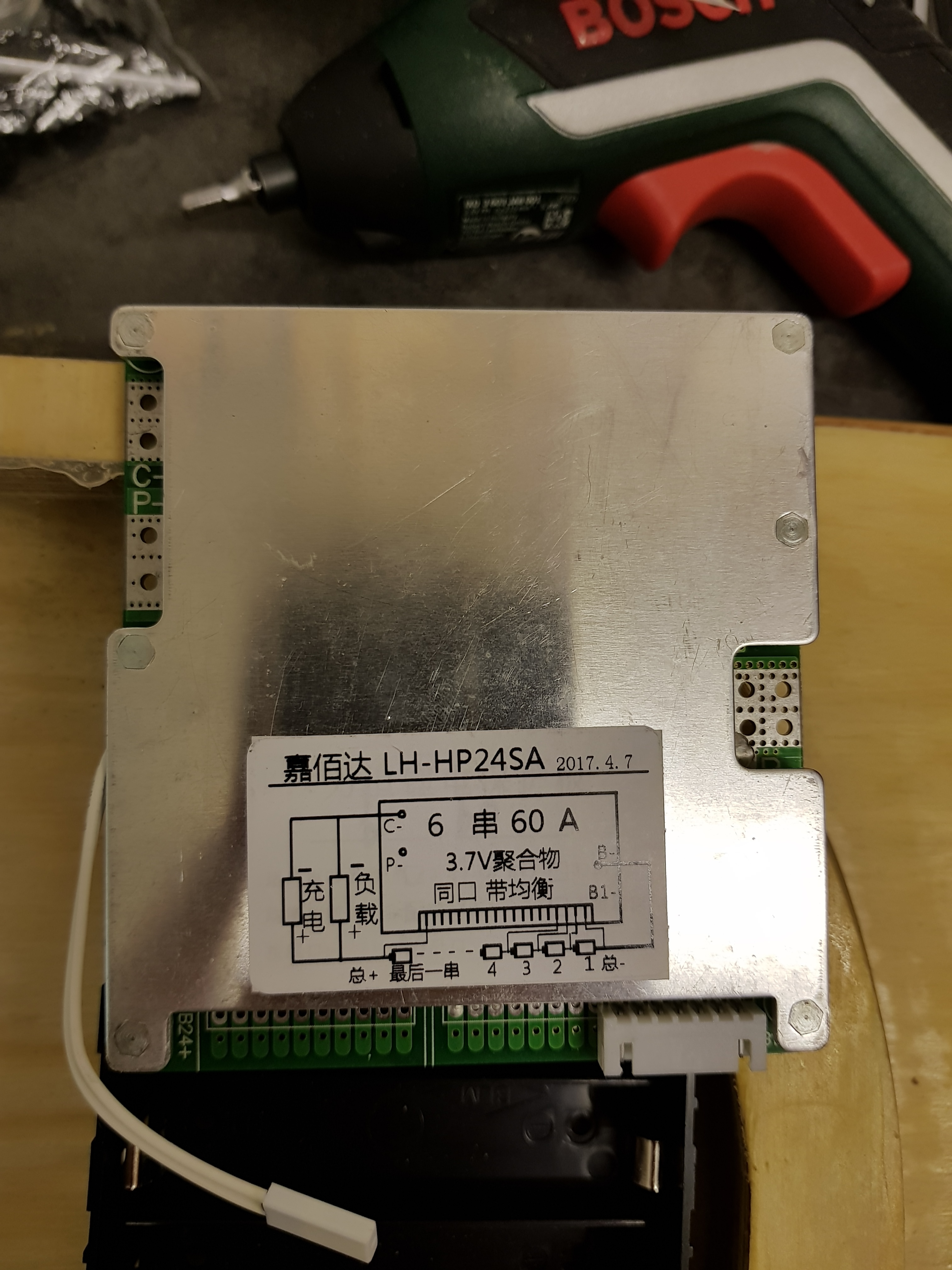
Thats what confused me the most, from what i understood and saw from other bms is that p- should be connected to engine or esc negativ but the wiring sheme i got from their site doesnt showed it.
Actually i would think this wiring would be correct, it´s confusing.
It is very confusing. Looks like a model S (charge and discharge on the same port) but it has C and P ports…
Either the diagram is wrong or is a model S. You should ask the seller.
I wired a 6s model S here:
That wiring is also wrong. You have the positives of esc and charger to one port of the bms and the negatives of esc and charger to the other one
What you want is the positives of esc and charger to battery positive and the negatives of esc and charger to p-
What we might have here is a bms with shared charge and discharge ports (just learned the are called model s) built in a shared pcb layout. Designed for either model s or for the “whatever You call the usual bms with separated ports”. Just like they do with the cell count where they design the pcb for a big cell count and just add the balancing components for the particular count they are building for.
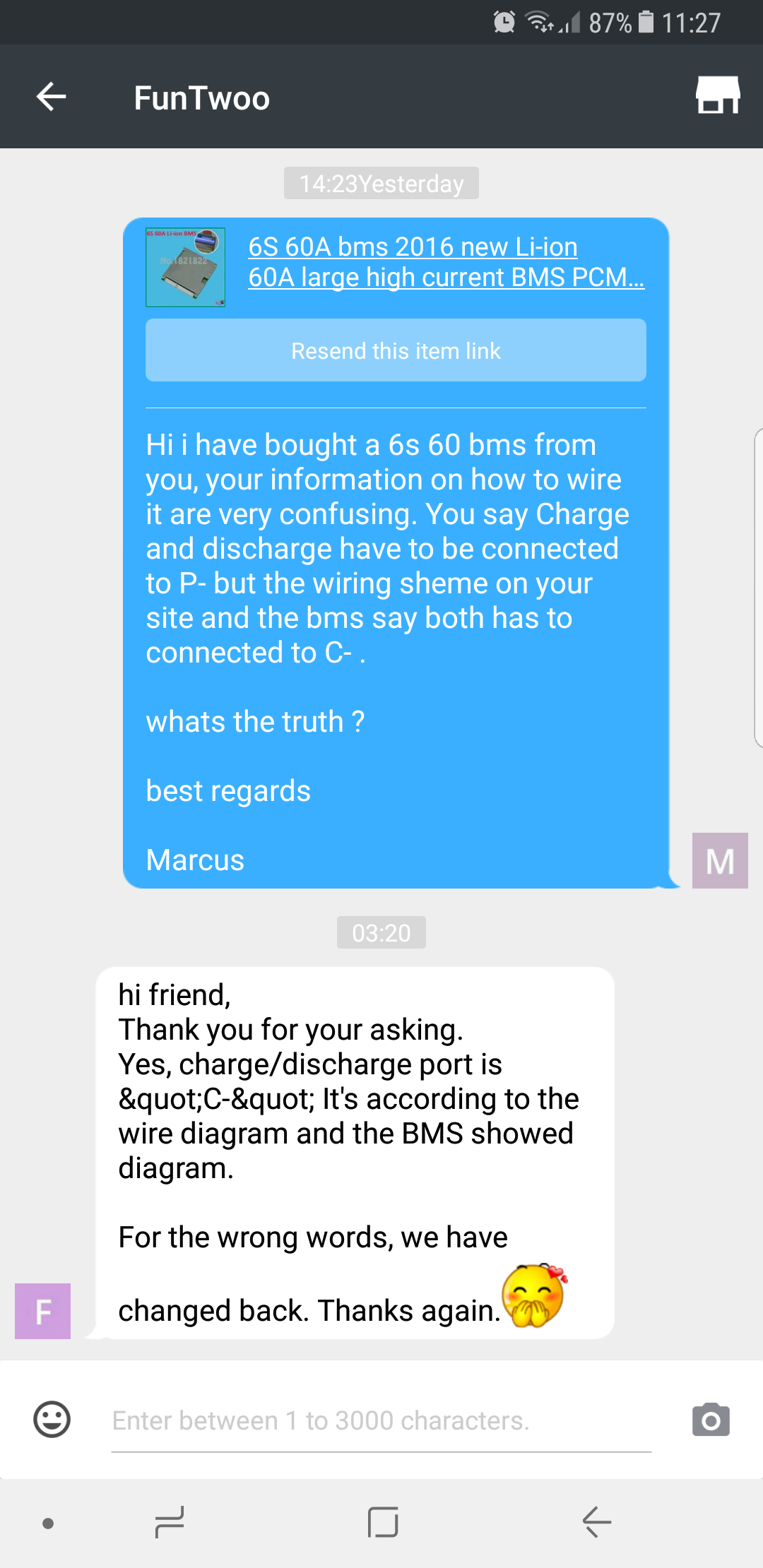
I Found something in the description of the Bms which made it pretty clear.
"This bms is used for Li-ion battery pack, The BMS charge and discharge ports are THE SAME PORT “P-”
So i tried again to do a more understandable wiring sheme with your tipps in mind but this time i´m not sure what to do with C-. I also used thick strings to mark where i´ll use 12awg wire. But i guess @rojitor is right and C- will not be connected.
“1. Before you make the pack, please test and match the cell’s voltage,capacity and resistance.
2.The diagram showed thick cable, please use the thick wire.
3.The balance wire sequence is from B1- B1- connect to general negative,the second wire connect the first series positive
4.When you connect the balance wire, please unplug all the wires ,then connect the wires step by step.
5. Connection sequence: Connect B- wire to battery pack negative ,then connect balance wires and plug in. Connect P- & C- and
and then test the general voltage and C-with battery pack positive voltage whether the same. if yes, then it’s OK.”
Just what you did in the diagram. connect nothing to it. Probably it goes to no where in the bms.
Nitpicking a bit now.
You should add a switch to the vmeter do it doesn’t drain your battery.
Personal opinion. Even if you use the esc switch. I would add a loopkey in case of emergency. For a simple jankoff quick switch
And some of the wire colours are technically the other way round, but as long as you follow the paths all is okay. Be sure to connect the esc charger and vmeter red positive to the battery+ and the blacks to the p-
Yeah i got that wrong with the color sheme i really thought red is suposed to be negativ wire. Again something learned.
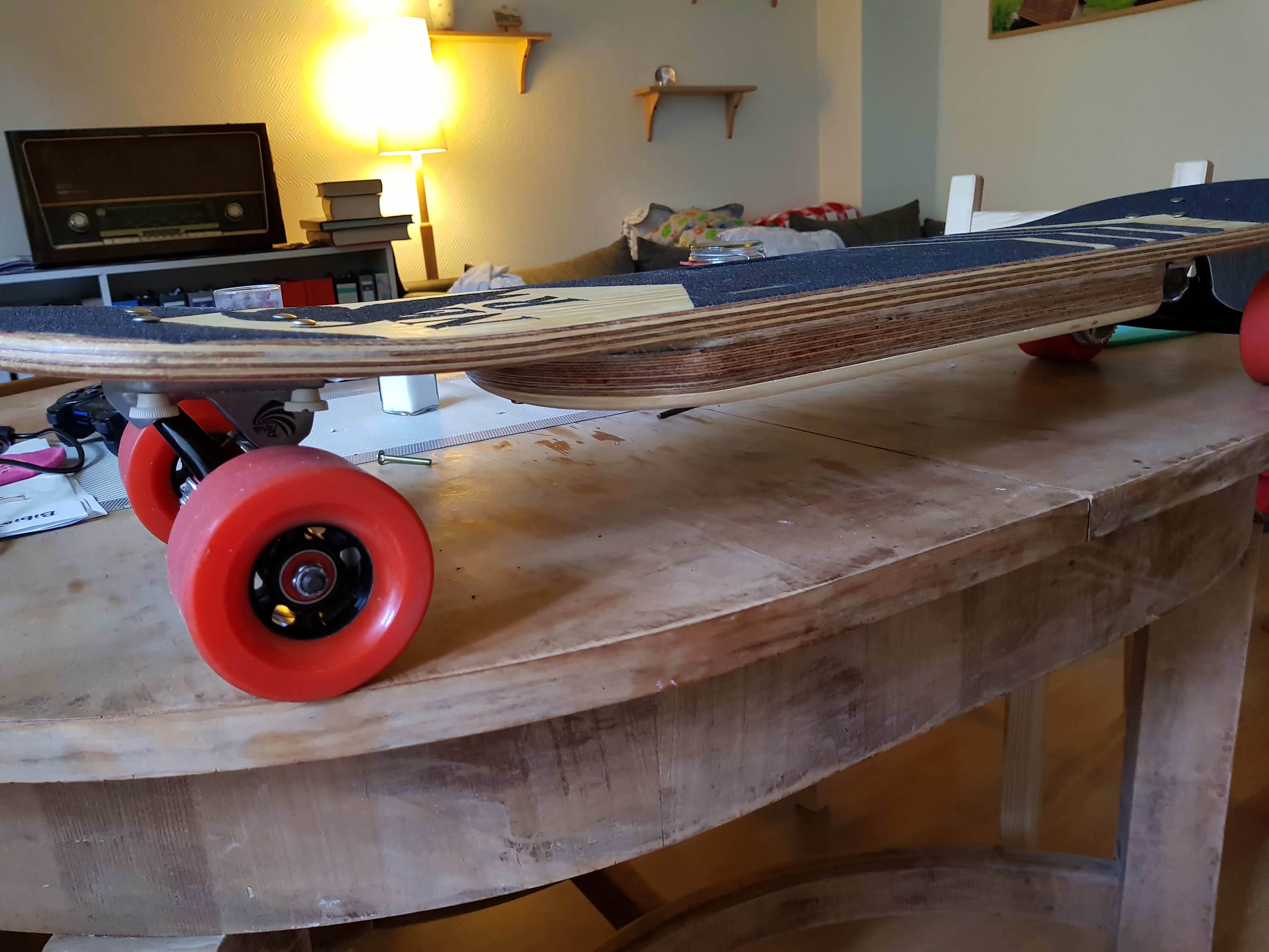
I’ve taken my time and wired everything up which was quite
Frustrating because all soldered conections were lose, i had to find another way to connect everything which looks horrible but works.
Systems are running and the board runs well BUT i don’t know if my bms is properly Working. When i connect the charger nothing happens while its connected to p- .
So i gave it a try and connected it to C- and it themed to starting to load until a little bang scared the out of me and i cut it off. (In both cases, C- and P-, the balance leds were not working.)
And here i am again, dont know what to do and especially dont know how to figure out if my bms is working properly.
So yesterday i tried the hole evening to get my bms working but for some reason i was not successful.
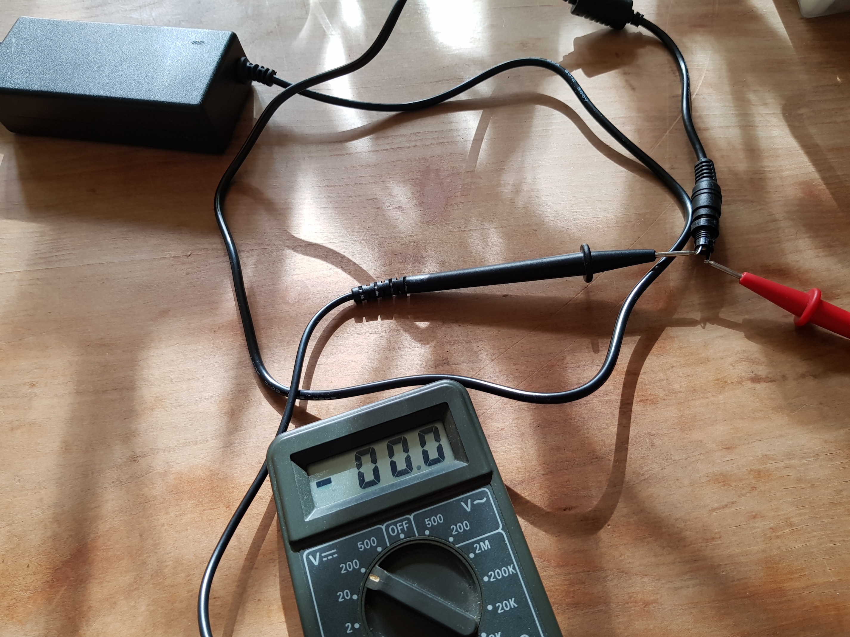
At first i checked my bms wiring just like @rojitor did in his video by and got 3,3V, 6,6V, 10,1V, 13,5V, 16,9, 20,2. I then reconnected my bms starting with B- then balancer plug then C-. And result is the same as before. The board works but it wont charge at all.
I’m now pretty frustrated and don’t know how to go on from here. If somebody has a hint for me on what to do next i would highly appreciate.
Thats what i was thinking too but i’m not 100% sure how to check it. Shouldnt my voltmeter show 24V here ? Because it does not.
But why does the green light shine whenever i plug it into my board ? And why should my charger be broken he is brand new, maybe because of the wrong wiring before ?
Yeah. I’m 99% sure your charger is broken. The led is on because the bms is feeding power to the charger and I’m guessing it is not protected against power going in through the charger out. Maybe that is why it broke in the first place. Didn’t simmering pop once when you connected something?