A friend with a knowledge of electronics made me. It’s plugged into the receiver.
2 Likes
Does he have a tutorial for it? I really want to know how this works 
7 Likes
You can use an Arduino as an add-on between the receiver and Vesc. The Arduino can read the ppm(I assume) input and determine what state the vesc is in.
3 Likes
solidgeek just put a snip of code that might help. I did similar with different style remote but pretty much map the throttle, anything idle (val) blink led and brake(Val) led on. On analog stick you can even incorporate turn signals, but sure a 3 way switch would work too
3 Likes

This might help you on making those brake lights, Done by @Nowind on his carver https://www.electric-skateboard.builders/t/trampa-street-carver-nowind-build-history/15192/101?u=partypoison
4 Likes
This is some next level shit man! He should make these to sell, I’d buy haha.
3 Likes
These Look Awesome!!!
3 Likes
And what do you do if there is a problem with the Arduino ? You can’t use your esk8 then because your PWM signal does not reach the VESC anymore ?
I really really think it’s a bad idea to put some electronic (thus potential problems thus less safety for you) between the receiver and the VESC but it’s just maybe me. I did LED braking system on my build and I have nothing between VESC and receiver. There is at least to different ways to achieve that, can you find them ?
PS : I said “between the receiver and Vesc” because it’s what you stated, meaning PPM is going to Arduino only and Arduino transfers it to VESC next. Is this what you think of (because my answer is based on that  )
)
3 Likes
It is connected to the receiver in parallel using a Y-cable. And a friend told me that the module of the LED braking system is not Arduino.
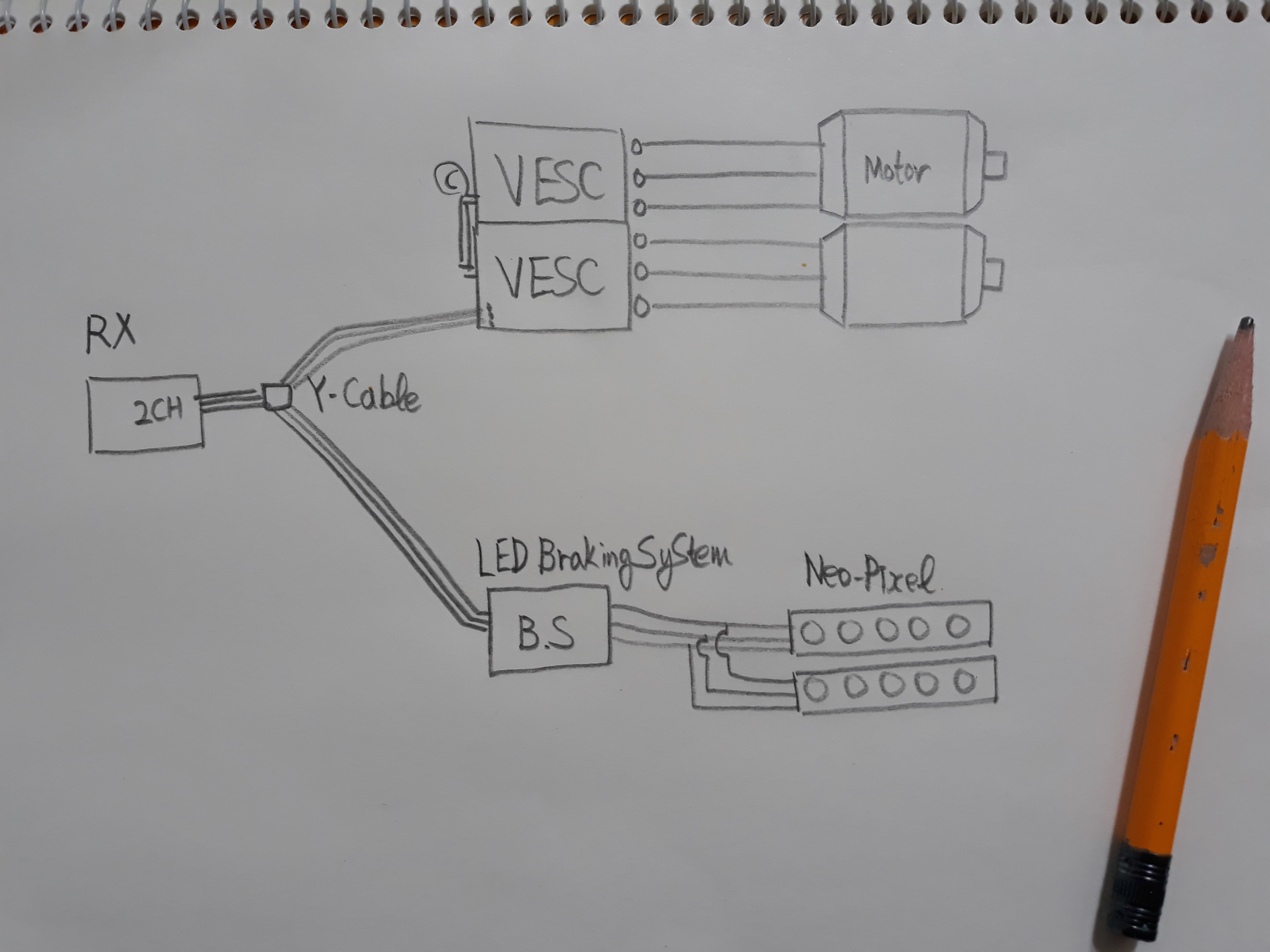
I have drawn the connection structure.


It is a LED braking system module made by a friend.
5 Likes
do you have a circuit diagram of the pcb? Cheers
3 Likes
Hey Lunar, it is one of the solution to do it. I guessed it was done like this but @ZackoryCramer said “between the receiver and Vesc” so I added my post-scriptum to be sure he was aware it was not “between” but “in parallel”.
Nice job from your friend. Don’t know if you can easily change thresholds or colors but even the capa is here (to protect) and it’s even smaller than an arduino pro mini, good point !
4 Likes
I saw four wires on this PCB and plug the LED pattern into the USB connection.
2 Likes
This PCB was made by the idea of a friend. I am an excellent guy who wants to learn.
2 Likes
Could you ask your friend to share some details about the PCB - I would like to use this. Had the same Idea using an Arduino - but why to invent the wheel, a second time.
4 Likes
Okay. I’ll ask him.
3 Likes

My E-longboard.
2 Likes
There is code to do the same light control within the 4.xx VESC somewhere… Ben had it on his board for a while. Think he even had turninglights controlled by left and right on the nrf nun-chuck.
3 Likes
i would think Ben had the settings in his nRF24 remote. this is snippet of code used to control driving lights with nun-chuck style. could easily add too to get additional lights/reaction
//–LIGHTS– //Throttle Throttle_PWM = analogRead(Throttle_in); if((Throttle_PWM) < 100){ digitalWrite(Throttle_out, LED_ON); } else{ digitalWrite(Throttle_out, LED_OFF); }
//L_Signal Signal_PWM = analogRead(Signal_in); if((Signal_PWM) > 100){
if (timeElapsed > interval_Blink){
ledState = !ledState; // toggle the state from HIGH to LOW to HIGH to LOW …
digitalWrite(L_Signal_out, ledState);
timeElapsed = 0; // reset the counter to 0 so the counting starts over…
}
}
//R_Signal
else if((Signal_PWM) < -100){
if (timeElapsed > interval_Blink){
ledState = !ledState; // toggle the state from HIGH to LOW to HIGH to LOW …
digitalWrite(R_Signal_out, ledState);
timeElapsed = 0; // reset the counter to 0 so the counting starts over…
}
}
else{
digitalWrite(L_Signal_out, LED_OFF);
digitalWrite(R_Signal_out, LED_OFF);
}
//********************************************************************
4 Likes
Yeah, you’re right. I never saw what was inbetween the VESC and the LEDs though. Was some led standard stripes and probably a LED driver that has a stepdown from the battery.
Thinking of implementing something similiar.
3 Likes