the way the anti-spark works it is only connected at that first few mm of plugging it in… afterwards it’s out of the way and not connected - right? or is it contacting and would then become the path (and quickly blow too)?
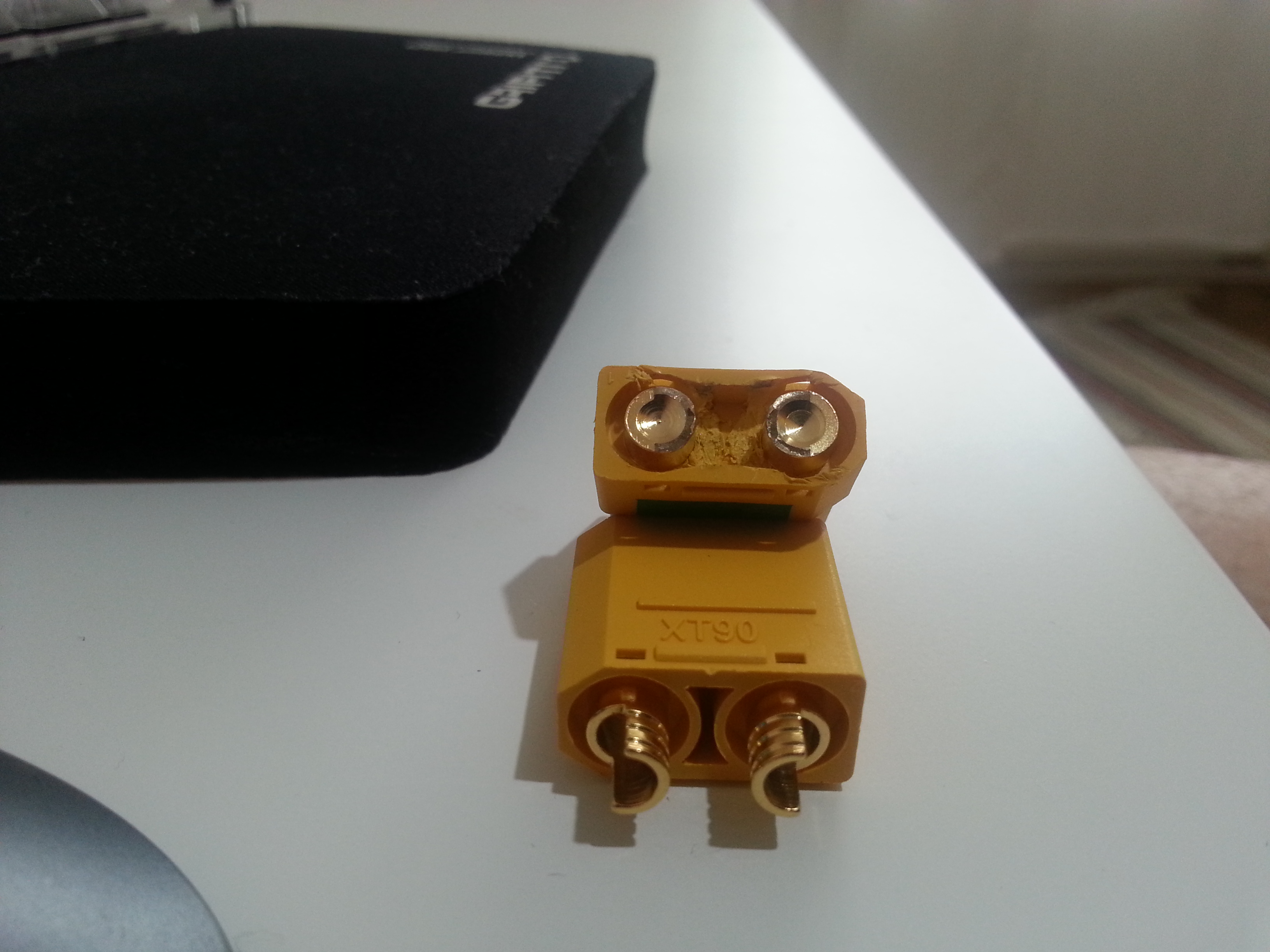
So I just got my xt90 in the mail today.
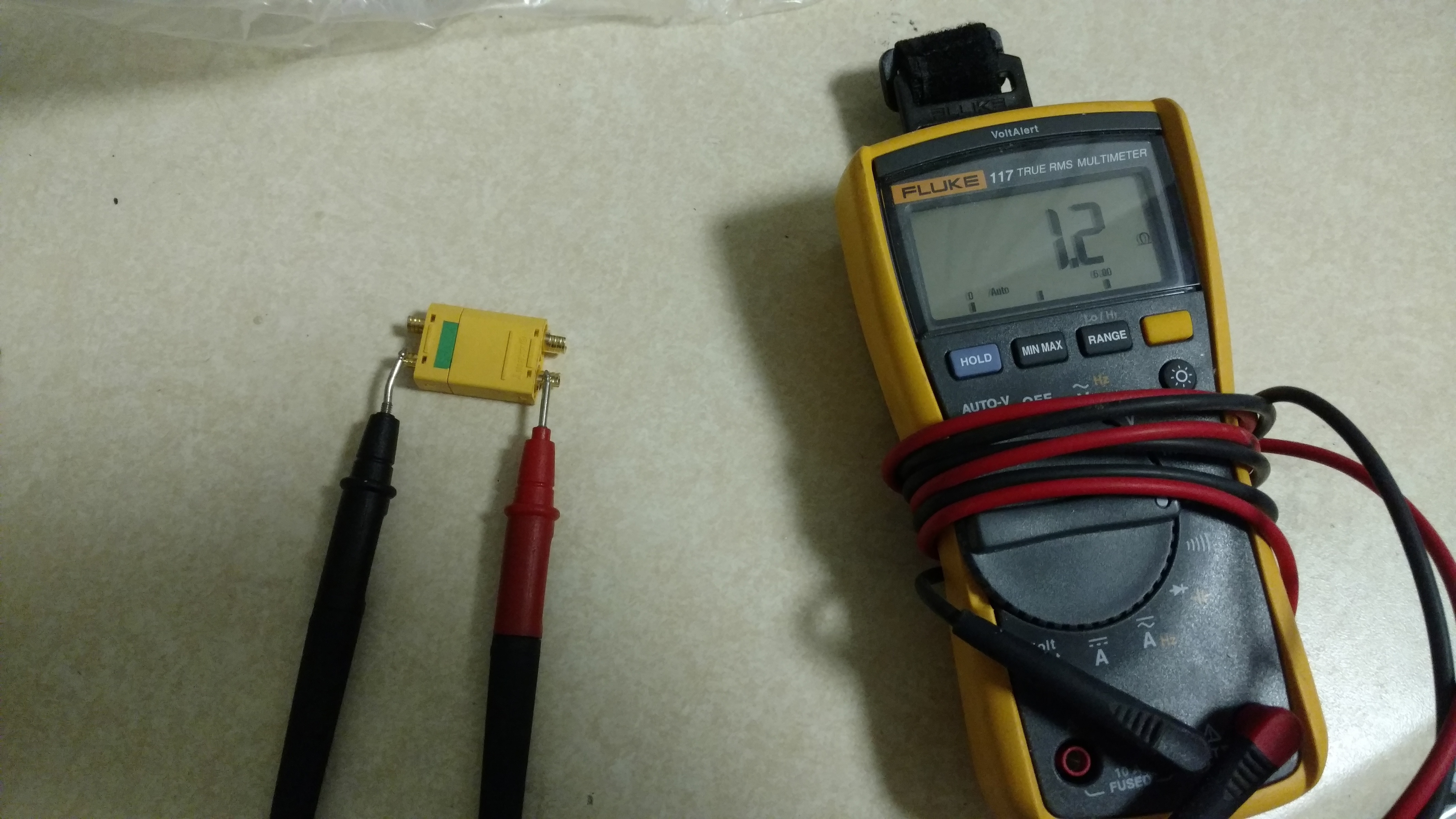
I did a resistance test and it is 6.7 at partial insertion and 1.2 (for my voltmeter .65 is a direct contact between the two leads).
So this means the resistor is not in use once the connection is full. Meaning if I put my fuse on there it should work no problem.
Ok, I’ve left this way too long, but, after testing my initial loop key (with the 680 ohm resistor), I was still getting spark when connecting the bullet connectors, unless I waited long enough for the VESC capacitors to charge up (think 6-10 seconds, counting in my head every time!).
So I modified it and replaced it with a 47 ohm resistor. This way, as soon as I plug the XT60 in, the VESC lights up, then I can close the bullet connectors. PLUS, there’s no spark anywhere! I’m running 9S1P if that helps anyone.
I have been doing mine this way for awhile, just never thought to post it.
I use a piece of 10g solid copper wire, bend the ends to fit tight in the XT90-S poles and then fill with solder. Then I cut the hald circles from the cap, super glue it in place and fill with hot glue. After its cooled some, just a little tacky, I push it in and then smooth the edges. It looks like this.
After that I print the XT90-S Fob cover, insert a paracord loop, melt the edges of the paracord together, fill the fob with hot glue and then insert the loop key. Let it cool and your good to go…ease to insert, easy to remote, the Fob protects the loop key.
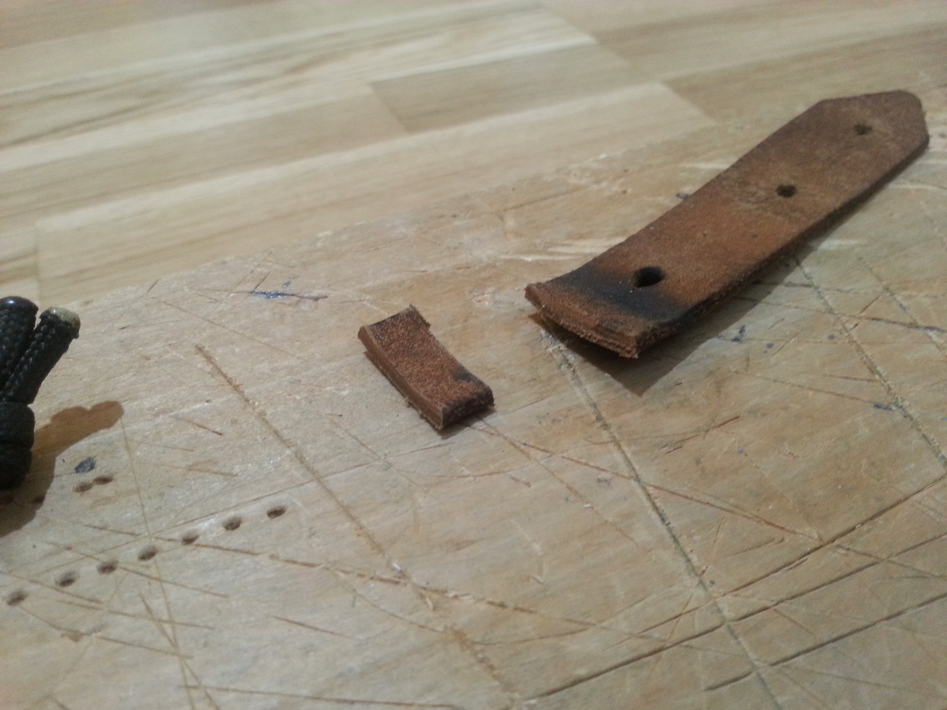
How does this solder joint look on my loop key? First time soldering in a long time. Also - can I just wrap a piece of Paracord around that for a pull tab or not?
Not really - for such a short run it should be fine. I would definitely go as thick as you can w/ whatever you use, and keep it as short as possible. That was the main reason i went with the solid copper - because it was direct point to point vs a loop of wire, and strong enough to then tug on w/ the paracord.
The only time i’ve heard of a problem is too thin of wire and a longer loop - more heat under load = bad.
Sorry, newbie question. The anti-spark loop key is supposed to go on the + wire, between the battery and the VESC, right ?
And it allows you to leave your battery in the board and acts like a on-off switch ?
Yes exactly! If you have a bms and charge port you should put it on the + wire in between the + of the charge port and the vesc. This way you can and should pull the key out when you are charging.