I cant remember exactly what value I used… I grabbed one at random from my pile… I think it may have been 100ohm? i think anything between 20ohm and 1kohm would probably work
1 Like
Thanks. I think I remember reading where someone had used a 50 or 100 ohm resistor, but I wasn’t sure if there was a “correct” size to use.
there is no “correct” size, just something to limit the inrush current a little bit so it doesn’t arc. there are many values that would work, and also depending on how many caps you have in your particular build…
@lowGuido, do you maybe have an example, or a pic of where you used this? I get the whole intermediary circuit that contains the resistor, but not sure how you would wire it so that the current flows normally (without resistance) after it’s plugged in.
I’ll take a photo tomorrow, but I’ll try to explain now. I take a male deans connector and solder the resistor across the terminals, then I short the two terminals of the female deans connector with a short loop. hook up the batteries and then attach the loop.
here’s a diagram.

2 Likes

Thanks for all the input. Here is a picture of my loop key I just finished. I used a 680 ohm resistor, as this was the closest I had to the one used in the actual XT90s plug (I think they use a 470, or 520 ohm one).

I finished it off with bullet connectors to close the loop. So to turn everything off, I just unplug the XT60 plug and can leave my batteries connected without issues.
I will provide more feedback on it once I’ve actually tested it.
4 Likes
Where is the resistor / how does it work ?
If you look closely on the first pic (it shows on the 2nd too), you’ll see I’ve soldered the resistor between the two terminals. So essentially, when you first plug it in with the bullet connector unplugged, the current will flow through the resistor (albeit at a much lower volume than without it). Once you plug in the bullet connector, current flows normally through the circuit, bypassing the resistor, since current takes the path with least resistance.
The other plug (male XT60) will be connected to the positive wires between batteries and VESC (as per the first post in this thread)
Right, now I see the resistor. So it’s a two-step process, first the bullet and then the loop key, right ?
first the XT60, then the bullet.
Love the idea bro, I plan on building something very similar. I have a question though, in the place where you soldered the copper cable to connect the two sides of the xt90, could I solder in a fuse instead? Basically right now I have a large fuse online on my negative power cable before the VESC. It’s 50 amps and made for a car stereo. It’s just so massive and annoyingly in the way. But if I was to put a nice small fuse, like one used on vedders anti spark board, 40 amp 50v I think. Would that work, or am I missing something in the way power travels?
@Rasmukri - that should work! The main concern i would have is resistance and heat.
I’ll see if i can grab one of the fuses i have and see how it might fit on the back of the XT90. Neat idea.
As always - having a spare to swap (anti-spark or not) is good peace of mind.
I’m not sure what you are proposing will work. a fuse and an anti spark resistor both serve different purposes.
I think you would have to put the fuse inline further down not in parallel with the resistor.
I cant see why it would be a problem. I mean its just closing the circuit, so instead of closing the circuit with a solid wire why not close the circuit with a fuse? Seems like putting it farther down the line would be no different. Power goes the easiest way possible and that will be through the fuse not the resistor, (after it has completed its job). I mean I’m no Engineer but I’ve been working on car and home wiring for quite some time. Resistors yes they always give me a bit of research before i do anything but i see no logical reason why a fused link would in any way not work. Think about it regardless of where the fuse is on the circuit the Same amount of amps will be passing through it.
by putting a fuse in parallel with the resistor you are changing the circuit. the fuse would still be the path of least resistance so in an over current situation it would probably still blow. but the amount of current required to blow it would change, and once its blown it would not break the circuit like a fuse is supposed to, because the resistor still completes the circuit. the most likely following sonario would be that the resistor would get really hot and also blow.
[quote=“rasmukri, post:26, topic:204”] I mean I’m no Engineer [/quote] True.
No, no, Nope no.
Hey LG - are you sure?
the way the anti-spark works it is only connected at that first few mm of plugging it in… afterwards it’s out of the way and not connected - right? or is it contacting and would then become the path (and quickly blow too)?
I’m no engineer…
if you are using an XT90-S that is the case. but not for the ones in the image above where the resistor is in parallel.
I apologise if that’s what you meant originally, I was looking at the pictures directly above with the resistor in parallel.
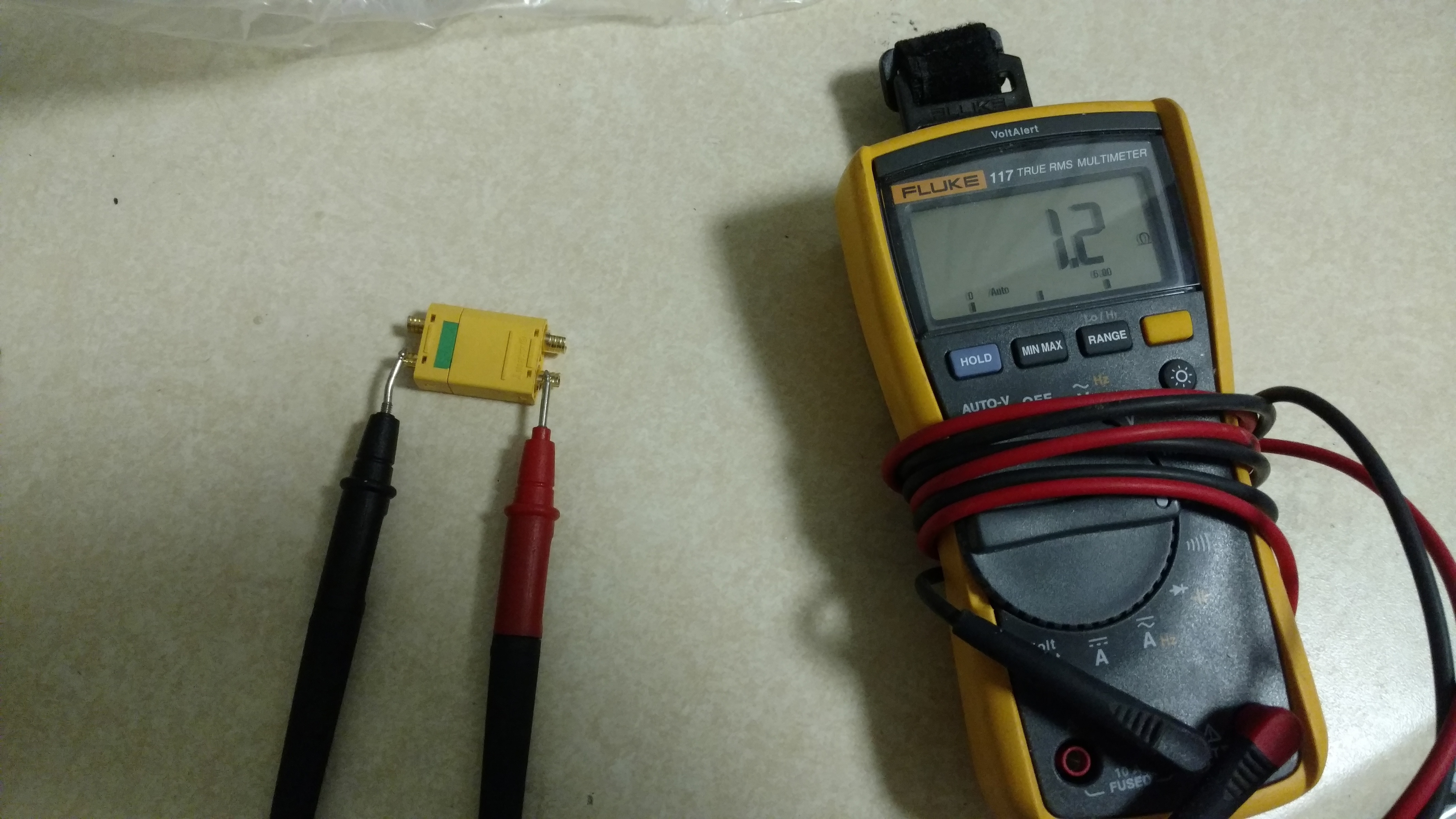
So I just got my xt90 in the mail today. I did a resistance test and it is 6.7 at partial insertion and 1.2 (for my voltmeter .65 is a direct contact between the two leads). So this means the resistor is not in use once the connection is full. Meaning if I put my fuse on there it should work no problem.


3 Likes