It’s pretty much just about where the heat is generated.
And then there is how many ways you can have the current flow to the next series cell pack, AKA do you have single or multiple parallel wires or double thickness for example for the high current segments to minimize the losses in the high current segments.
Plus voltage drop on the higher resistance strips, (smaller strip = higher resistance) which affects overall performance by a little I would believe. Not enough to be an issue by itself but if you were already having voltage sag issues, they would only be exacerbated by it.
I think the resistance of a cell is typically less than these nickel connectors, can the connection resistances all be added and, maybe through extrapolating using the cell’s own resistance and sag graph, the sag of the pack can be revealed…and it would be much more than the simple cells? Sag would be an ohms equation incorporating the resistance of the cells and connections?
They can be added. It’s a little more complicated than that though as internal resistance of cells change depending on their state of charge and temperature. It is very complex to try to model
Here’s an article for modeling li-ion internal resistance under different conditions, just to get an idea what all kinds of things are going on in the cell.
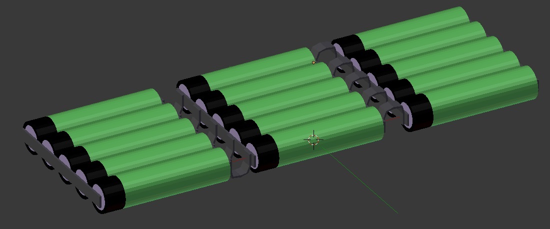
After various discussions with myself and others, this is also how I built my 10s5p battery pack. Directly welded the taps of the “serial cells” so I have 5 individual rows, then added a cross bar in order to be able to balance the pack.
From the “termination cross bar” I even have two individual, parallel connections to my VESCs.
Main reason was to reduce the current flow in the wires.
I think building a pack as in post 12 is slightly more effort and more difficult, however it has advantages:
reduced current in the connections
if done properly the pack has some flex
it’s even possible to extend the pack, e.g. from 4p to 5p.
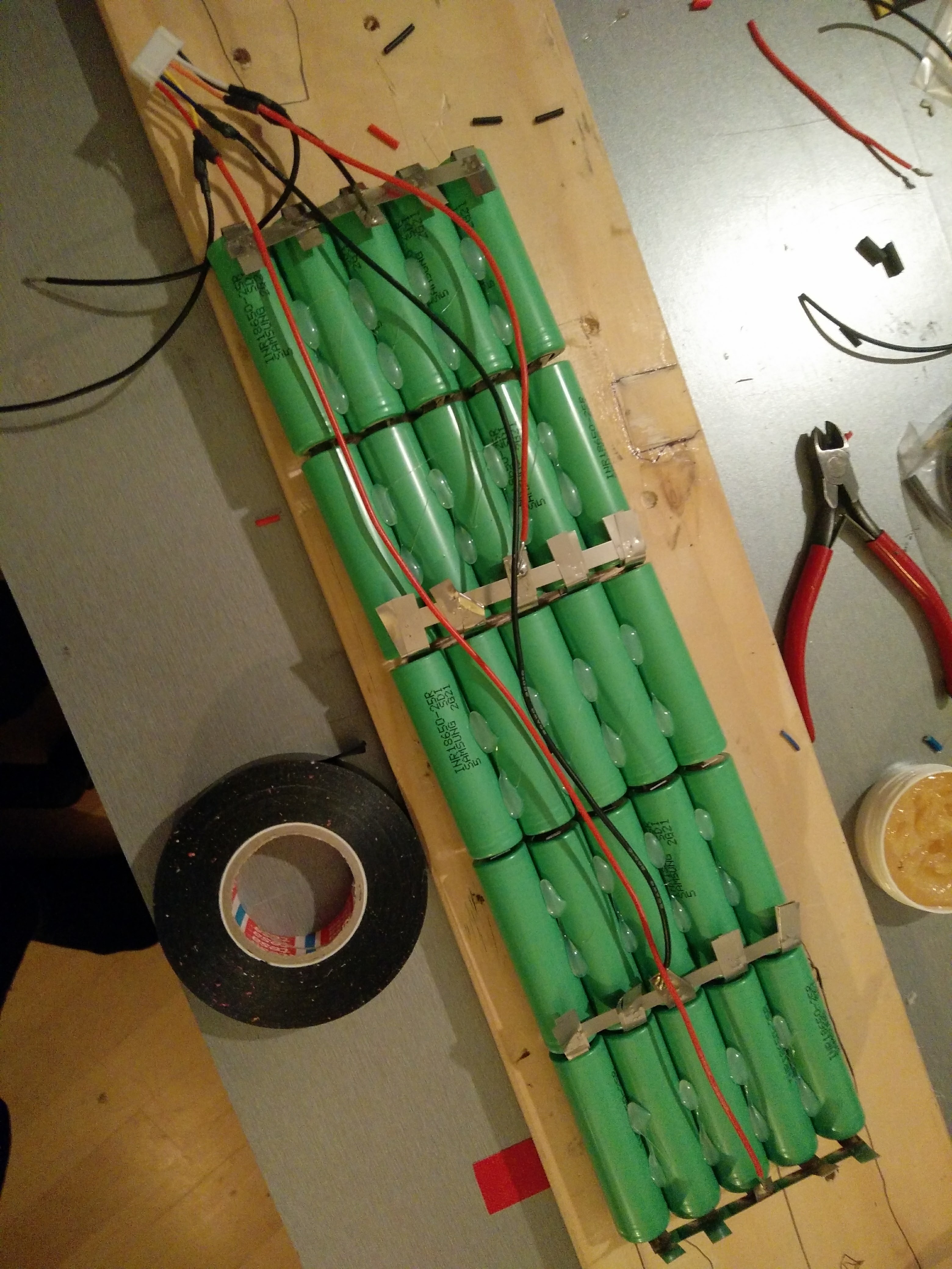
Sure, it’s all VERY DIY, no fancy tools. I was going to document all of it in a build log - but what the hell, I will never get around doing it anyway. So here you go.
Started with hot-glueing 5 cells, then another 5. Then spot-welded those taps. Note, my cells came with pre-welded taps in z-form
In the back my DIY spot welder. Don’t do this at home if you don’t know exactly what you’re doing. I don’t recommend it, but it worked. To the right a small 2s5p pack with the cross bar.
Then I added two AWG 10 wires with plugs to connect the two 5s5p packs plus two AWG 10 terminals to two VESCs. Tape and shrink wrap.
The two 5s5p packs are pretty flexible, enough for a medium flex board.
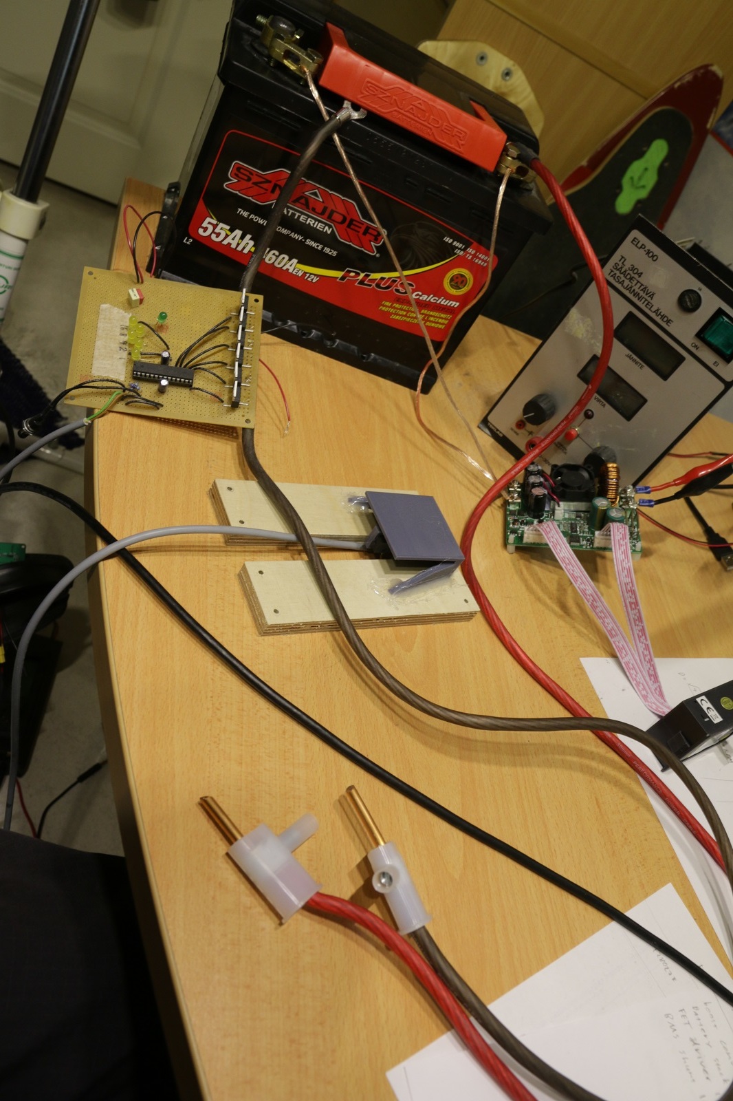
Decided one day that I needed to spot weld a pack together so checked around online for good platform and then saw this on my usual check for new articles on hackaday: http://hackaday.com/2016/03/22/arduino-nano-runs-battery-spot-welder/ and coupled my own version of it together with components off of my shelf. Hella ghetto I admit, but it gives a configurable double short circuiting pulse for the battery triggered with a dead simple foot switch.
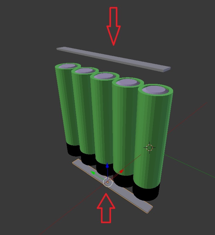
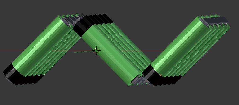
Anywhoo, I thought you would have done your battery pack welding like this:
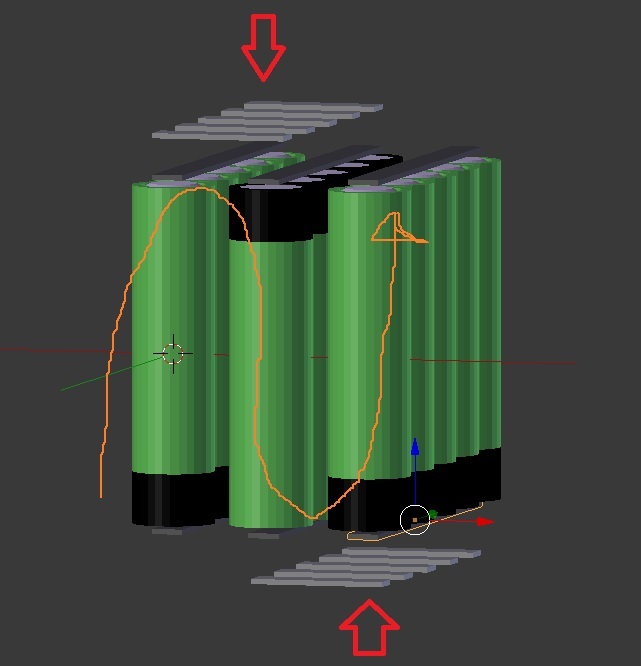
Then just fold the pack out (The bends are over emphasized on the lower pic for illustration purposes). Recommend adding the balance leads before doing that though.
I am not a pro when it comes to electromechanics so i have a silly question for the pros.
I would be interested if the current in these u turns create a inductance like it happens in the motor or does that only happen when it is a circle
I’m no pro but everything has inductance and capacitance to some degree. The inductance profuced being determined by the length and width of wire with shorter and fatter making less inductance. Maybe put the multimeter on inductance and check the whole pack
I think the coils of a motor or any conductor will reinforce the field so if you simply add a turn or loop to the battery wires it will increase. As u say. U can cut down the inductance by putting the plus and minus wires beside each other cancelling each other. the closer the better
Here’s a link to Vedder’s VESC6 analysis video with timecode pointing to the part where he demonstrates the wires inductance depending if it’s a big loop vs. both wires running parallel next to each other: https://youtu.be/x6lPdI9OVQg?t=13m4s
So technically yes. You would have extra inductance in your pack if you were to leave the parallel strips on such a round bend, but in reality you would push them pretty much together with a sharp bend and then the strips would be parallel and next to each other and you also have 5 parallel strips (in the case of the picture you pointed to), which would drop the total inductance caused by them to a 1/5.
In your diagram where the wires are Red will also augment their resistance correct ?
…Will their Higher resistance at red points change the way Current flows through the Pack ?
Will More current flow through batteries where heat is less ( not 10A on each cell) ??
i dont think the resistance of the red will increase much at all, it will get warmer and increase resistance slightly assuming that it’s not under specd and not getiting significantly hotter. I think the current from each cell should stay pretty much the same assuming the wiring will have only slight variations in its resistance at different points. I think more so the red will show increased heat and that is not good for cells and deteriorate them and will maybe unbalance cells over time.
maybe where the heat is less, so around the green area, the resistance will be a bit lower, so a bit less currrent will have to come from the branch of that paralleled cell to equal the rest, so the cells will not have to put out as much compared to the other paralleled cells with more resistance in their paralleled branch, and that will also keep them in better shape and unbalance the pack as well.