Vibrations, material fatigue, and one fateful strike.
1 Like
ahh, the good old trampa hammer’er’in
3 Likes
Not just for bearings! 
1 Like
I had to use hammer to hammer in metal part of spring retainer as it was spinning loose inside the plastic  So I guess that’s counts as hammered part too
Patent pending
1 Like
Hi everyone,
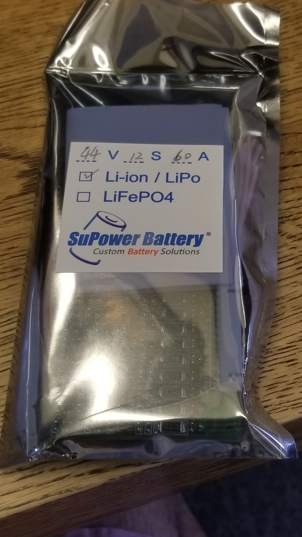
Got my batteries in and I’m starting to figure out how to put the electronics together. This is where I need some help from the community.
I’m using @Eboosted’s double stack enclosure and I’ll be fitting my 12s8p along with the BMS inside it. Focboxes are externally mounted.
General layout is as follows:

Series connections will be done using two 12awg wires. Balance connectors (not drawn) will be in the middle.
A column of batteries from that layout would look like this:
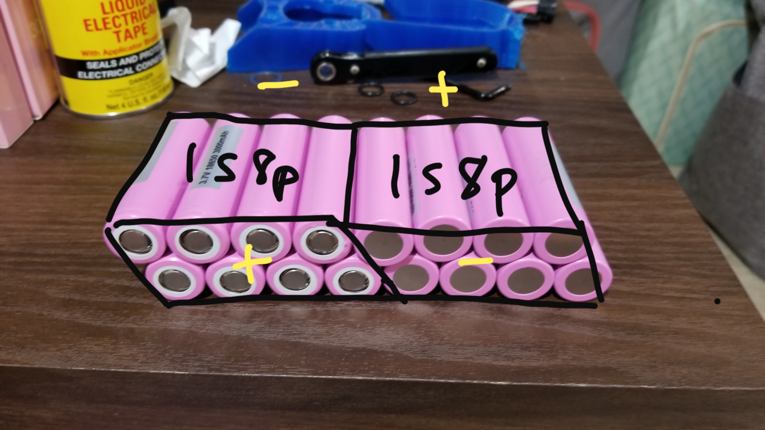
If this were the column of batteries nearest the BMS, the left 8p group would be the 1st cell in the series and the right 8p group would be the 12th cell.
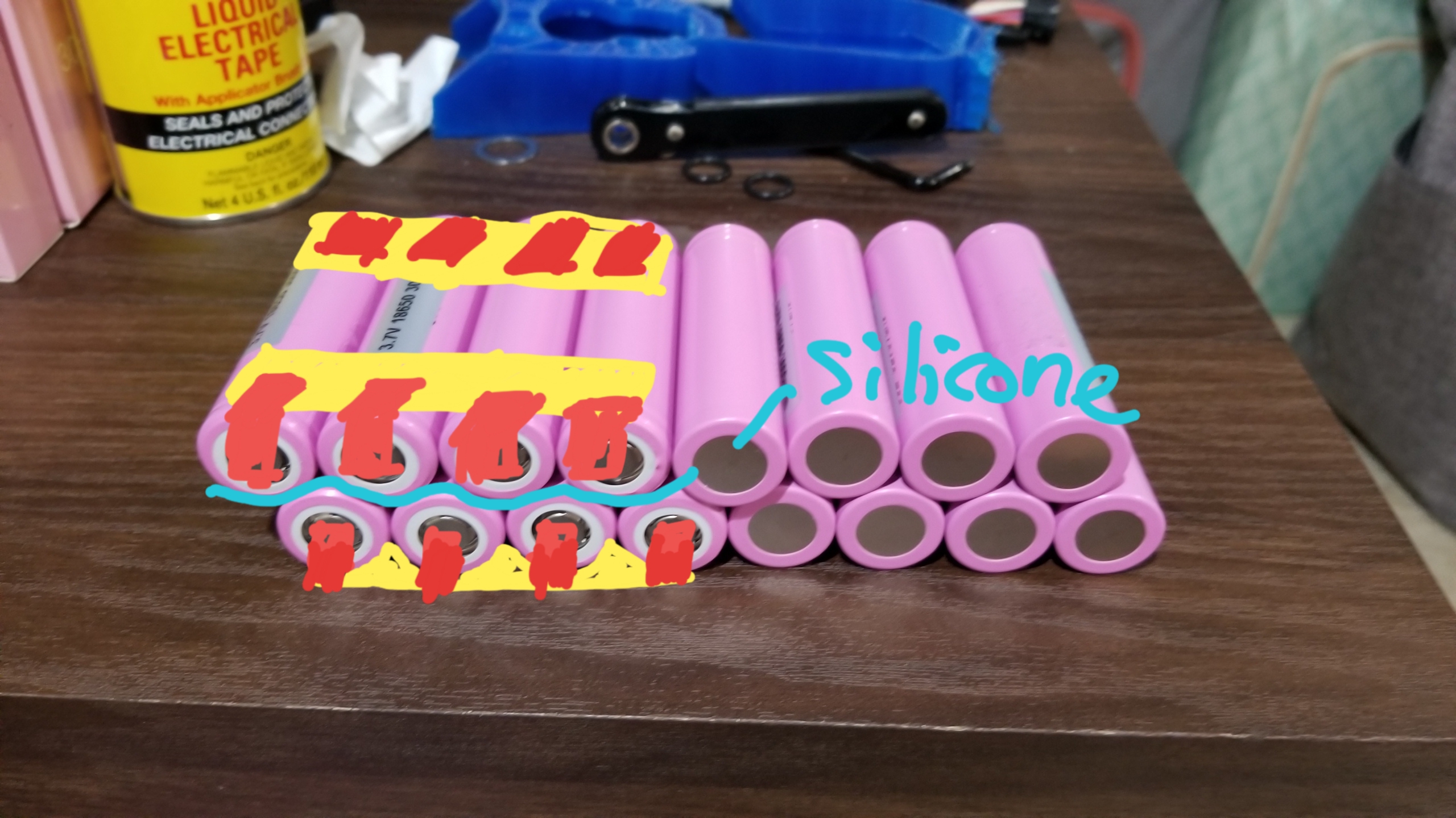
I plan on using a bus bar (probably a charging PCB) + nickel strips for each 4p side of a cell and add a layer of silicone between the two 4p layers like so:
Now here’s where I need feedback. I have to ideas on how to connect the two 4p packs into an 8p pack:
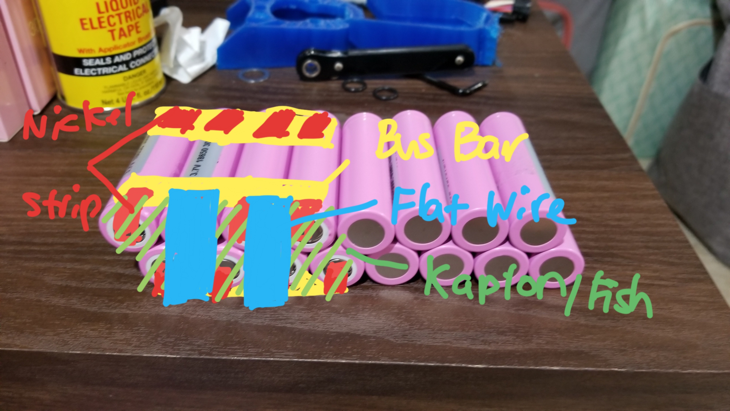
The first idea is to wrap the exposed strips and terminals with an insulating layer (kapton, fish, or both) then connect the top and bottom bus bars with two flat wires. This preserves the flexibility of the nickel strip + bus bar combination in that when a single cell in a pack goes bad, I can just remove that cell and its nickel strip from the bus bar and replace it with a new one. No need to ruin the existing welds on the other cells.
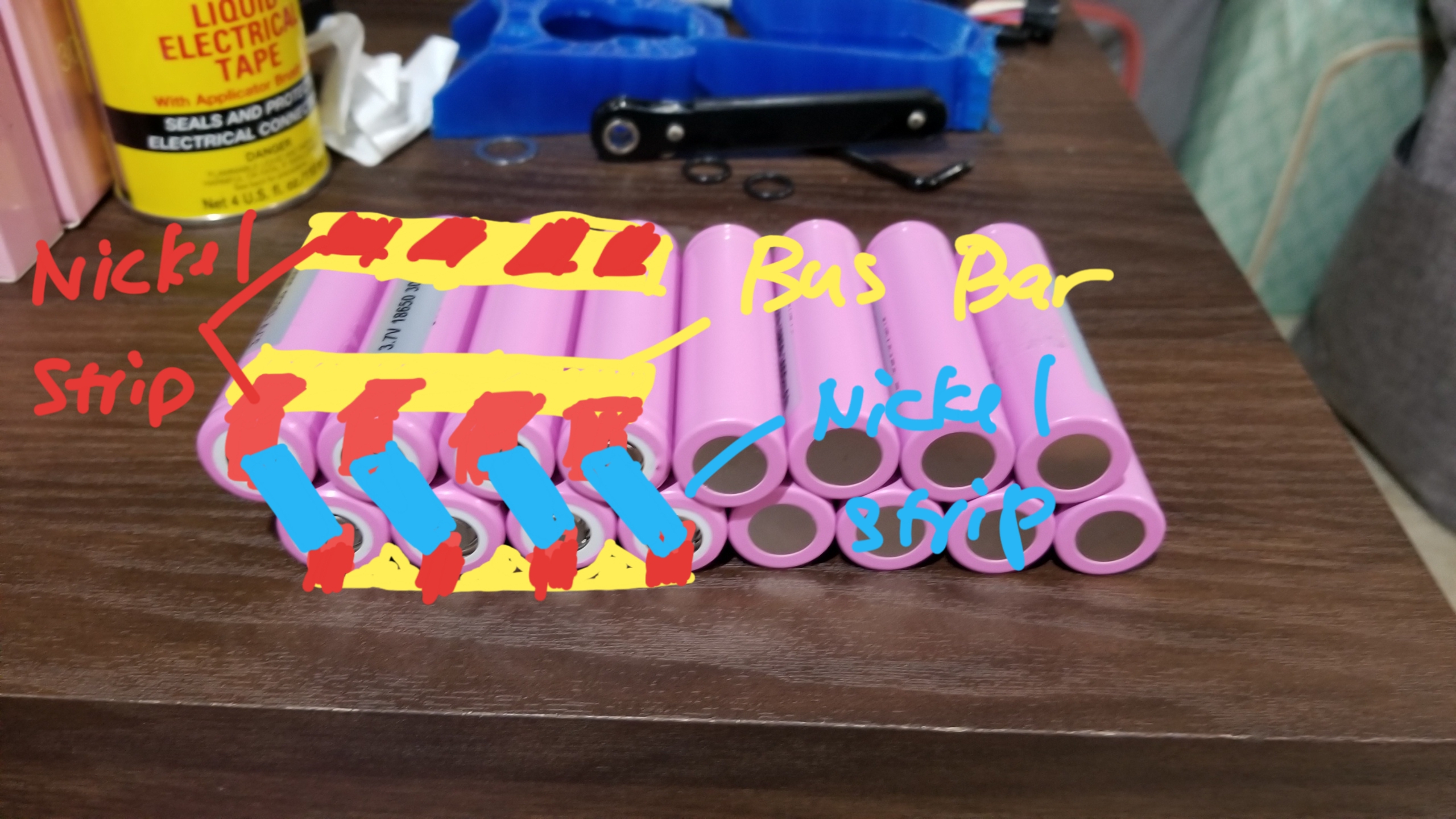
The second idea is keeping it simple and just welding each cell from one layer to the corresponding one at the bottom. I feel like this has less points of failure, but when once cell ends up being bad I’ll have to replace both that and the one it’s attached to from the other layer.
So yeah. Any help is welcome. Also tell me if I’m doing anything wrong.
2 Likes
You never mentioned the thickness of your nickel strips. What do you plan on using?
Edit: I like doubling up on .15 nickel strips for parallel connections. Then a single .2mm on each cell to connect to the pcb
None of these are Direct Drives. These are All Gear Drives
2 Likes
Alright Mr keyboard warrior, I’ll bite.

Etoxx calls it direct drive, Fatboy calls it gear drive. If I want to be politically correct, carvon and raptor drives are what’s called “direct drive”. But I’ve already grown accustomed to calling non belt and non chain drives as direct drive.
My understanding is carvons are direct drive ,@Kug3lis and @Nowind are gear drives, raptor 2 uses hub motors. Seems simple to me, am I missing something?
2 Likes
My fault dude , just wanted to ensure than anyone who came upon this thread would understand that none of those drives are Direct Drives. I am no warrior, I fight for no country.
Etoxx is wrong.
Fatboy is right
Yes. Carbons are the only DD that allow All 4 longboard wheels to be used. All other DD are hub motors so the Raptor 2 and Hummies are Techincally DD 1:1
Cool, I mean you shouldn’t since we should aspire to use correct terms for correct things since these build logs are look at by others but whatever. I meant no disrespect.
1 Like
No you’re good , Hub motors are , by the def , Direct Drives as they are 1:1 and Direct Drives :
can be applied to any motor which directly drives a load or rotor without transmission elements such as gears, pulleys or chains.
3 Likes
I think my supplier said 0.2mm thick 8mm wide. I’ll have to check.
0.20mm will require a higher pulse, transferring more heat
Aight, we cool. It’s just any DIYer I talk to in person knows what I’m talking about when I say direct drive, so it was never really an issue for me but you’re right someone reading this thread might get confused if they didn’t know their stuff.

So I rethought how I’d do my batteries. Instead of pcb’s on the top and bottom of the enclosure I might do a sole bus bar with bent nickel strips separated by a film of kapton / fish paper. Each series cell will be connected from bus bar to bus bar using two 12awg wires. Any issues with this design? Vibrations? Current draw of 8p on a single bus bar? Temps?
1 Like
Hey all,
I’ve been enjoying riding this thing too much that I’ve put off on updating my build thread. Anyway, here are the updates:
My original plan was to do a 12s8p top mount but @Eboosted just released a double stack version of his HS11 enclosure so that finally swayed me to do bottom mount.

The biggest problem I faced with this setup was the 150 amp bms that I already had. I figured if I cut off the heat sink a bit the pcb might still fit.

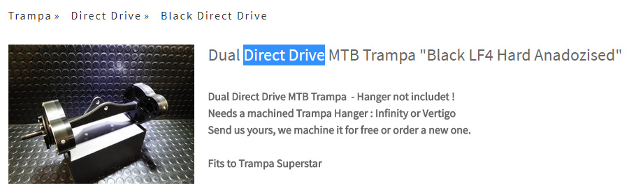
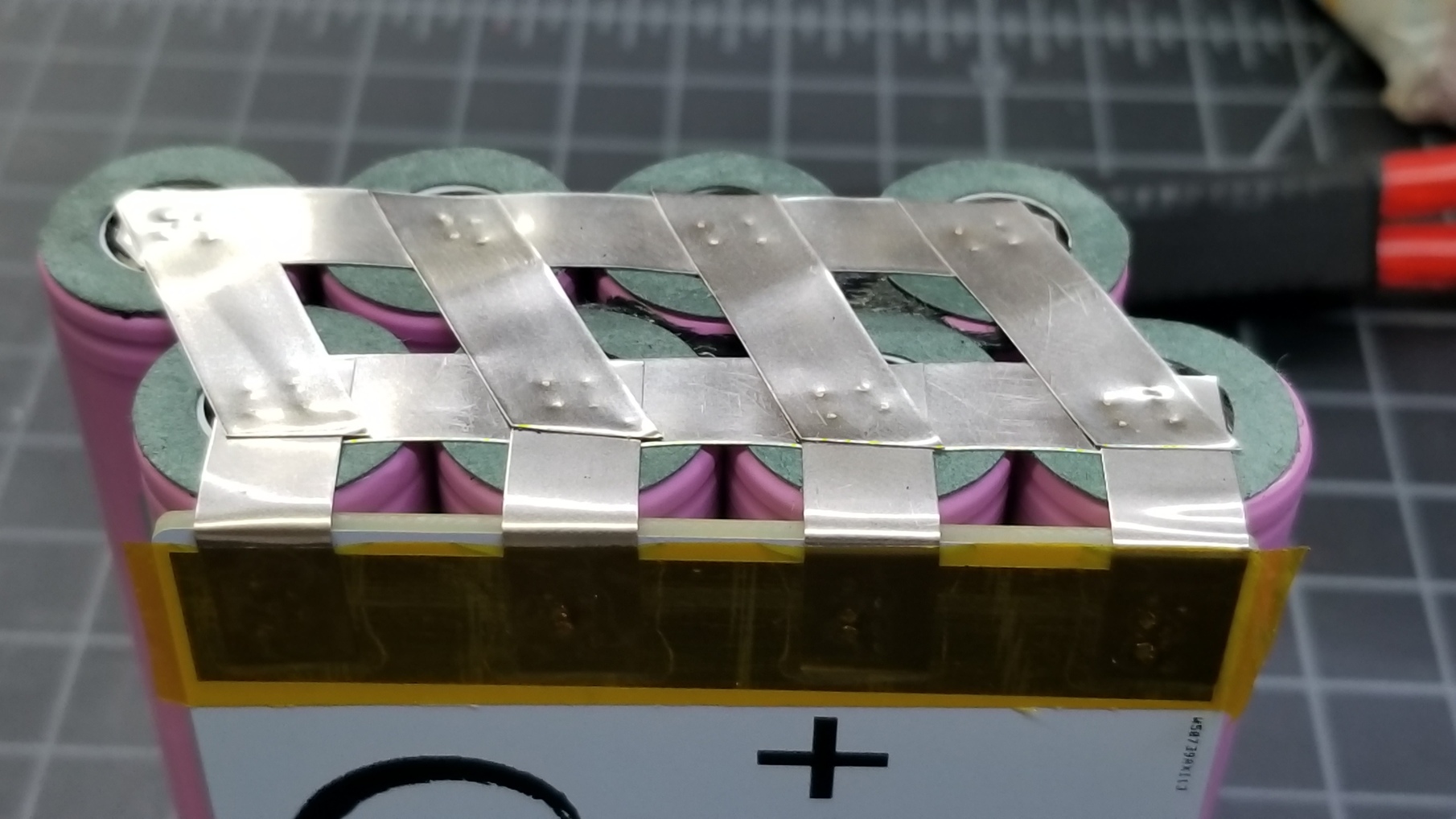
Battery building time. First I built the 4p packs

I got a hold of some pcb’s from @Kaly

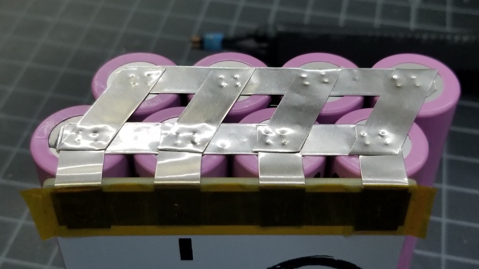
Test fitted them out on one of the 4p packs. I also took this time to build my 8p packs. I used Dow Corning 795 industrial strength silicone to bond two 4p packs as using silicone over hot glue helps with vibration dampening. At first I was skeptical when I was advised to use silicone, but shit is no joke, it’s used to hold glass windows.

If you saw my previous updates, I was trying to figure out how to build my 8p packs. Ended up being lazy and went the simple route.
Test fitted them out on the enclosure then I hit my first snag. I’ve posted about this on his enclosure thread, but the imperfection within the inside walls of the enclosure ended up pushing my cells inward

Ended up having to dremel a few mm to flatten the walls


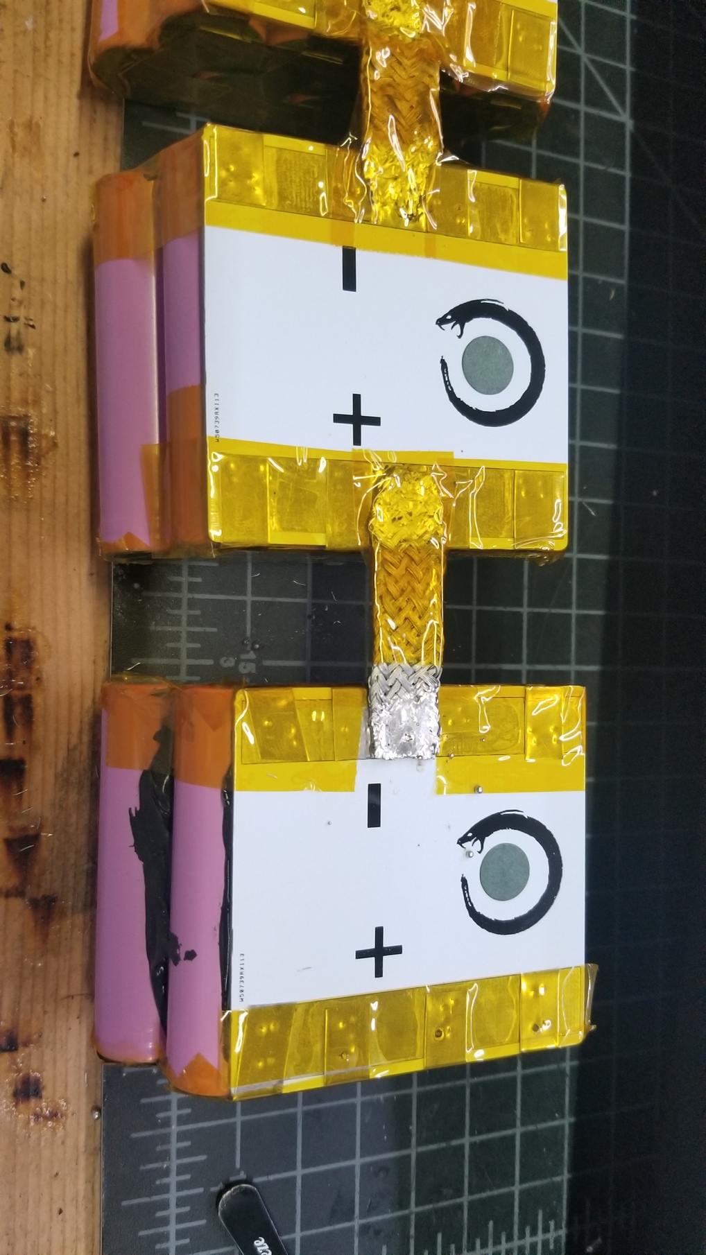
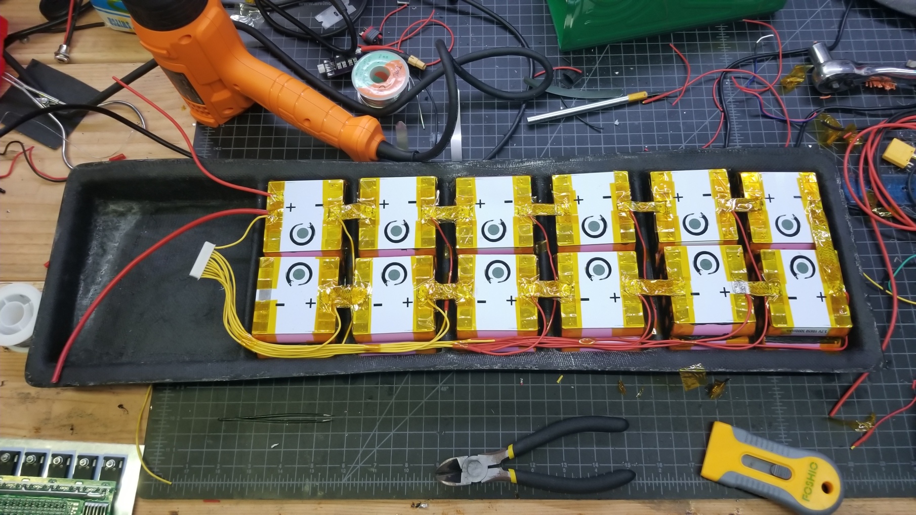
I used some flat braided wire to make the series connections. I was debating on using this over two 12 gage wires but ended up with this for simplicity.
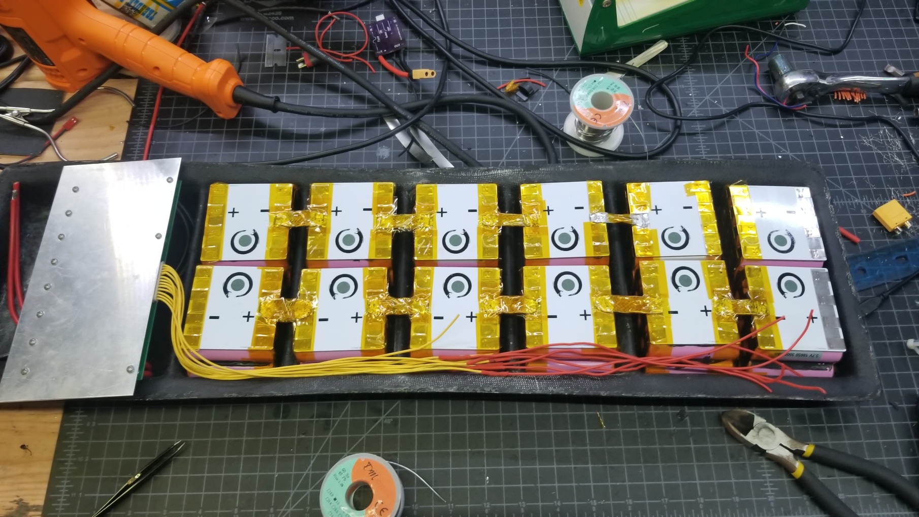
Now the balance cables. I used the channel on the side to route all of my balance cables. Looks cleaner that way plus it won’t have the enclosure pressing against it compared to having them run on top of the cells.
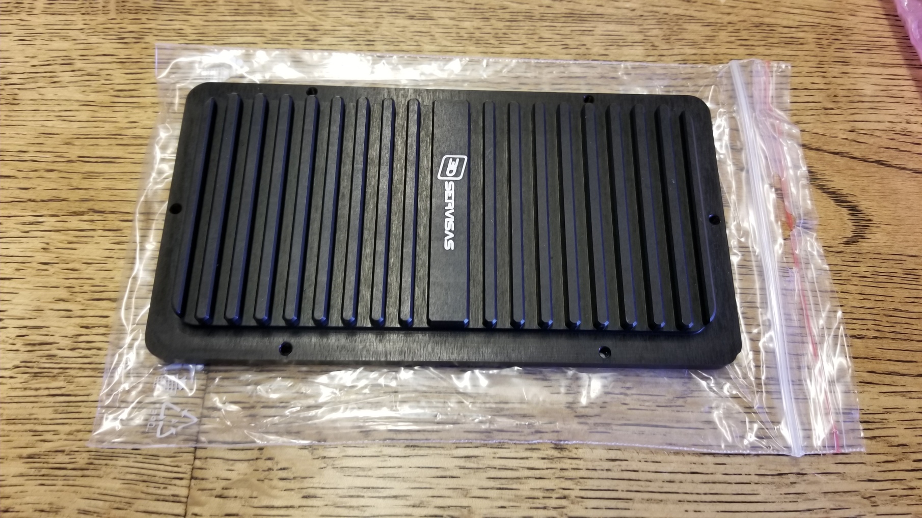
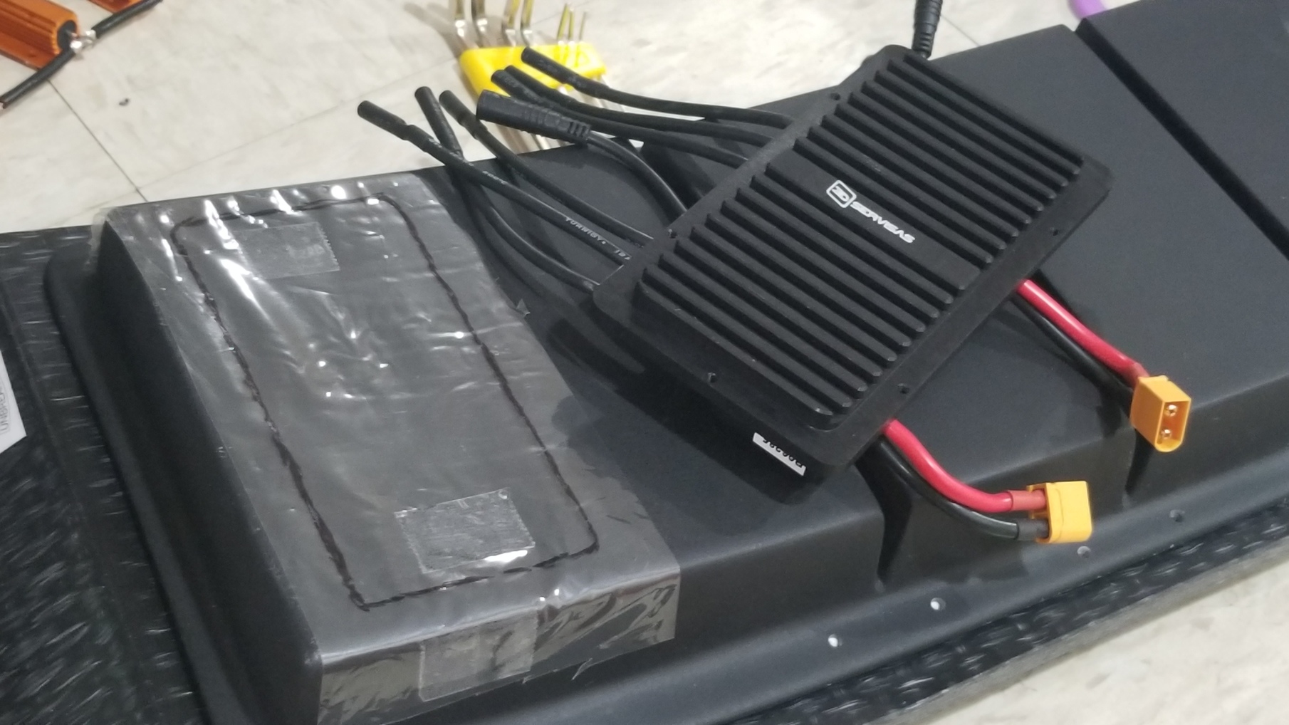
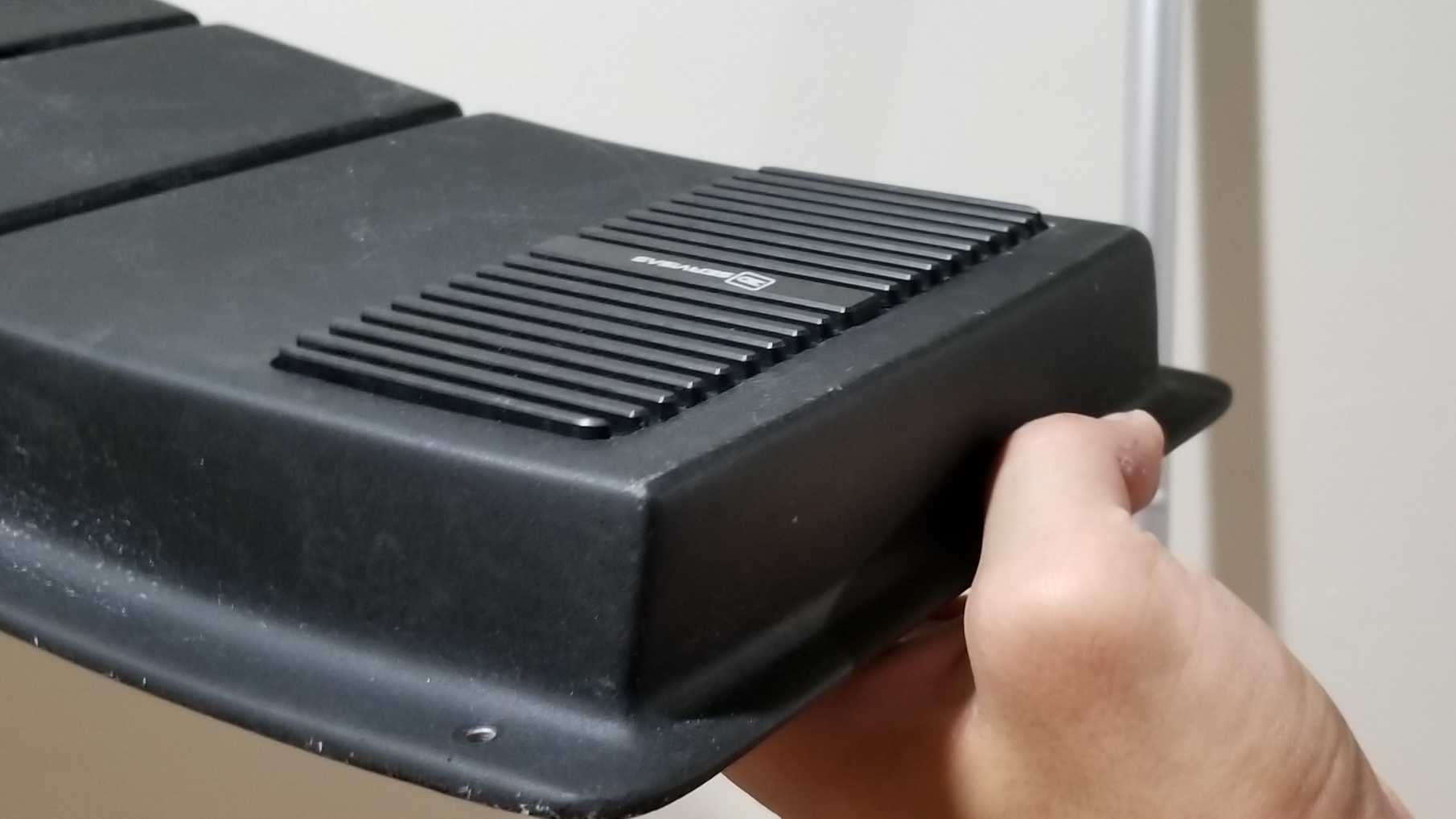
Enclosure time. I was originally going to use @Kug3lis’s top mounted dual focbox enclosure but he just released his evolve style bottom mount cooling plate, and me being myself jumped to try out the newest shiniest thing.
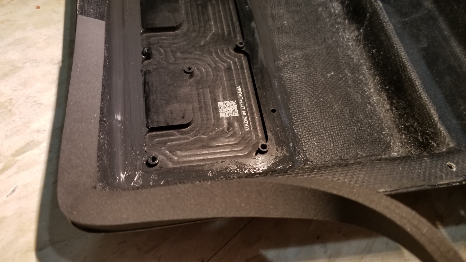
To make the hole for the cooling plate, I took a piece of plastic (the more rigid ones, think uniqlo underwear packaging) and traced an outline that I then taped on the enclosure.
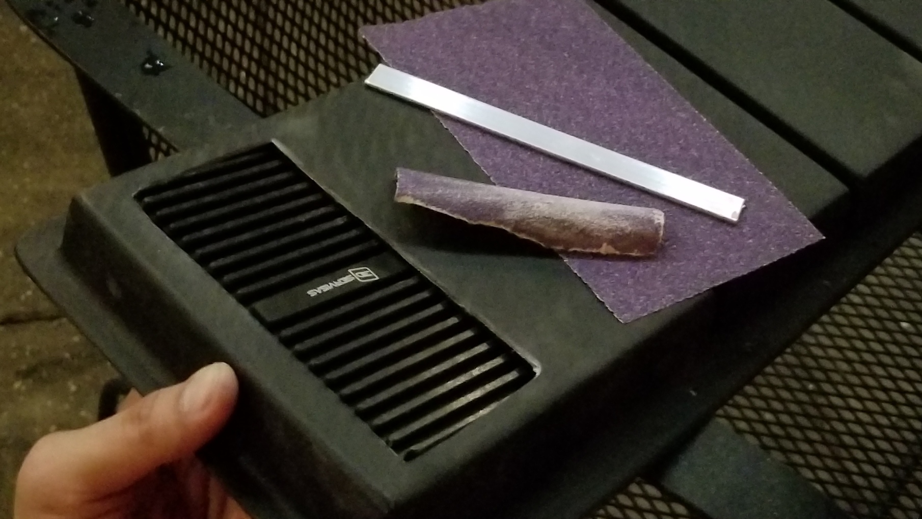
After dremel-ing the hole I used sand paper to get a nice fit.
Once more, I used some silicone to glue the cooling plate in place.
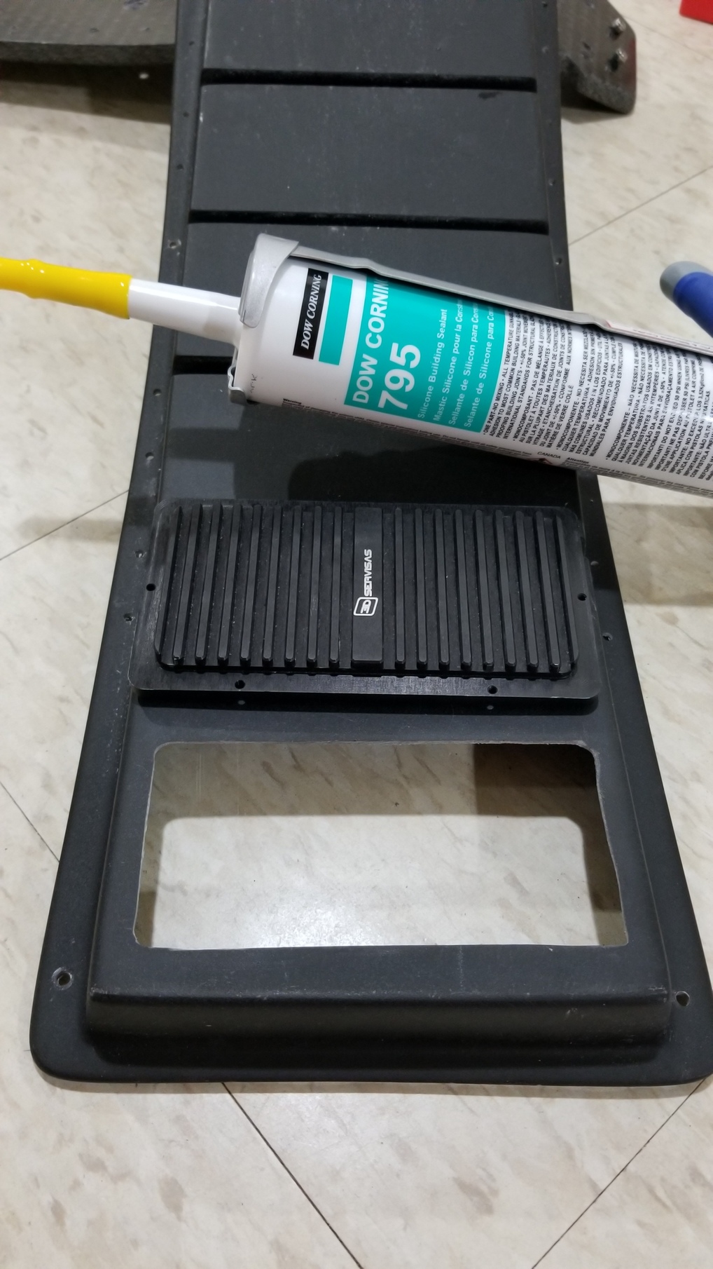
Also, waterproofing.

Came out really clean
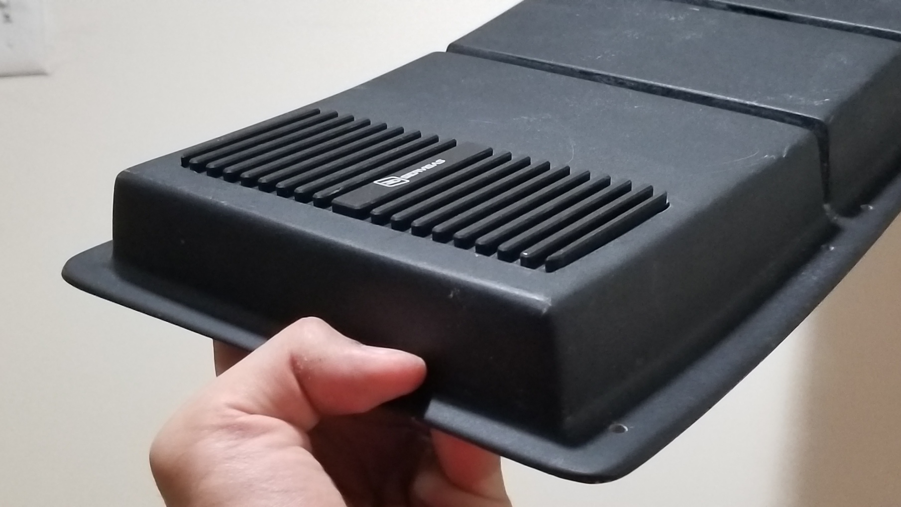
More waterproofing.

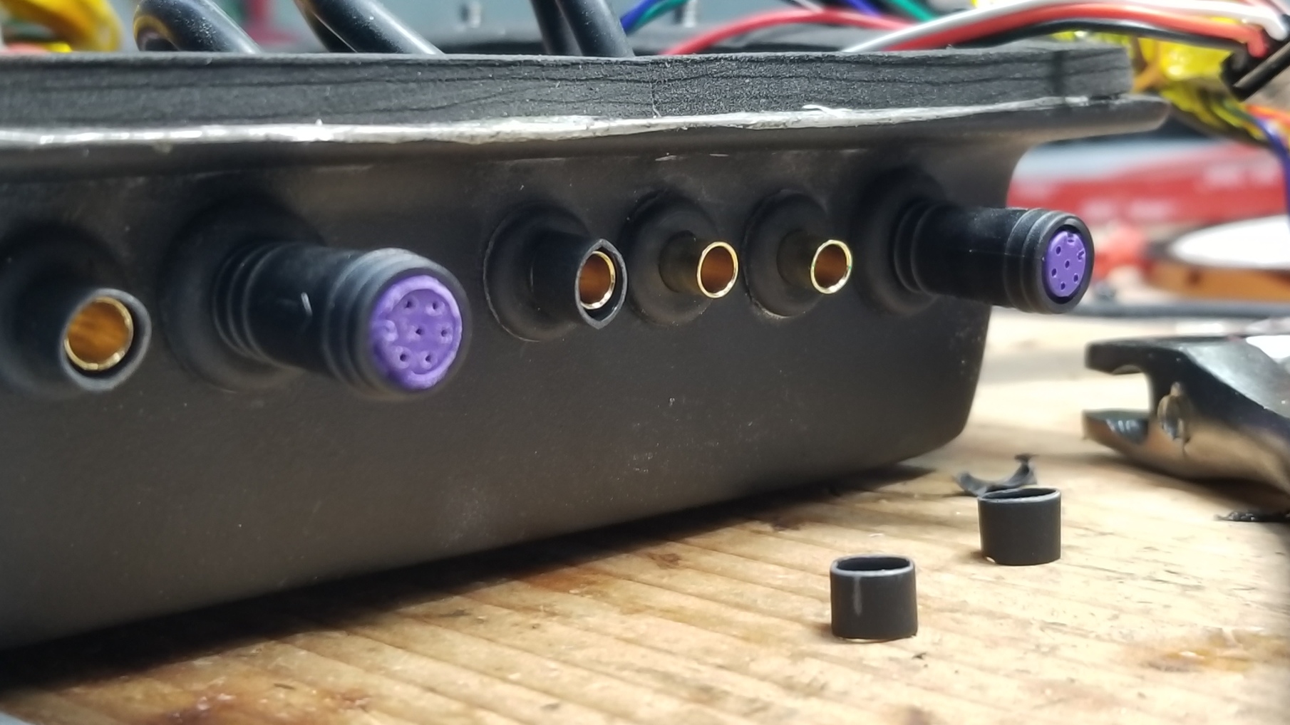
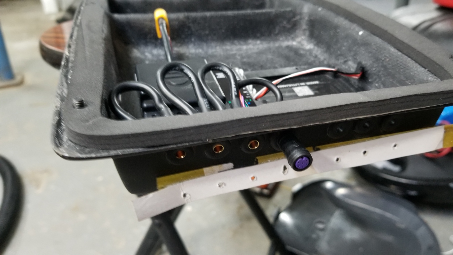
For the focbox wires, I used some rubber grommets.
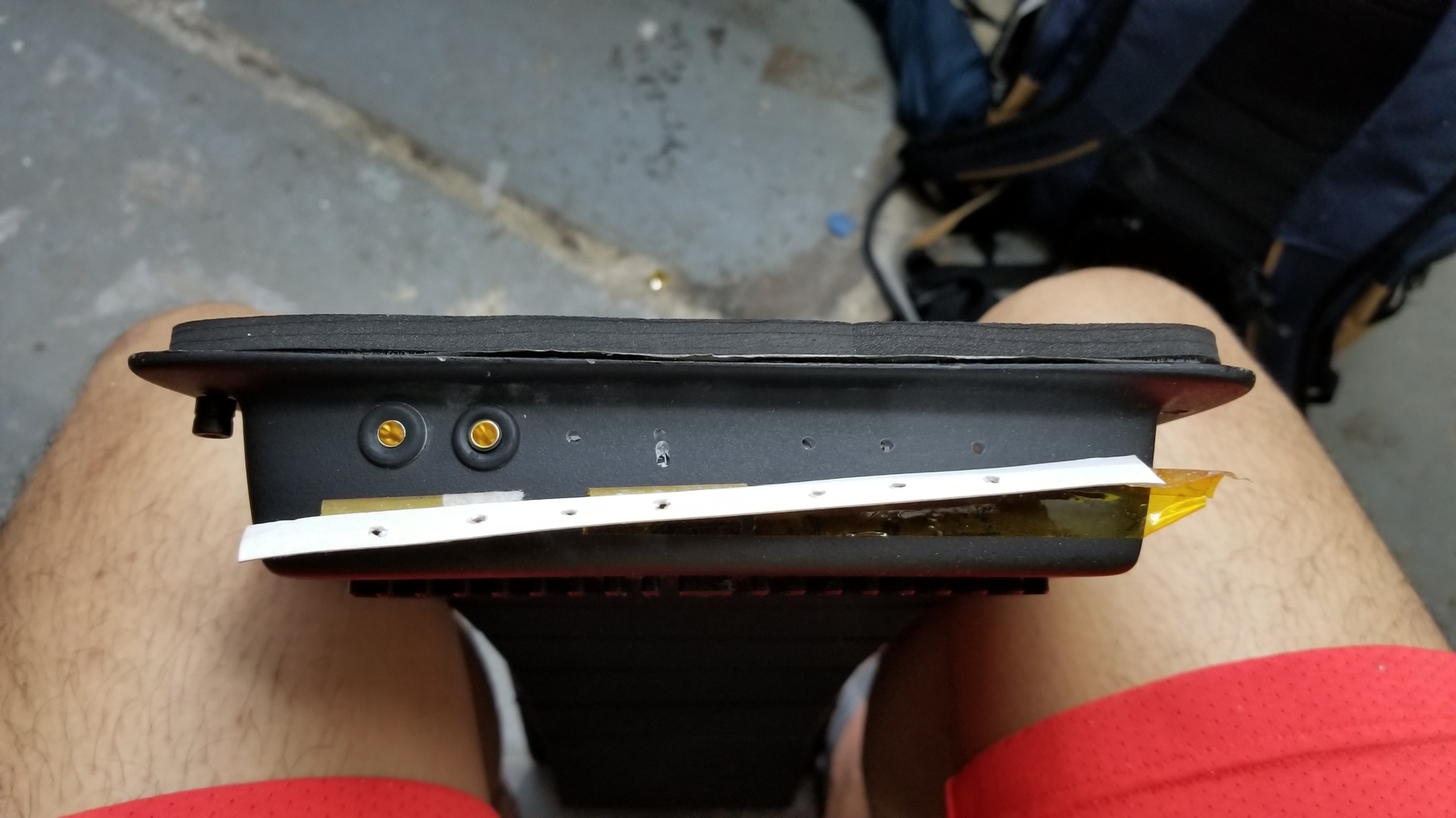
To make sure the phase wires don’t push in all the way when I insert the bullet connectors, I cut of some heat shrink off of the bullet connector, inserted the bullet connector through the grommet, and heat shrinked it again on the outside
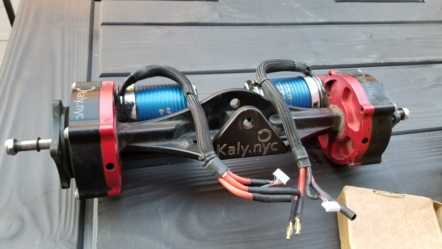
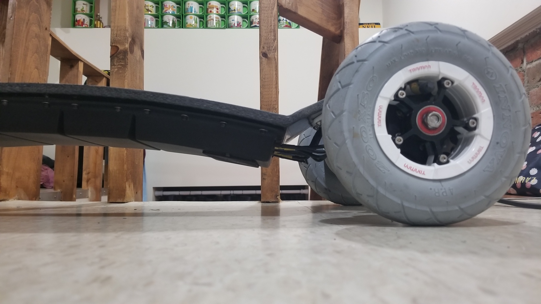
Also a few parts got changed along the way. I bought a used @Kaly direct drive and a smaller 60 amp bms

Unfortunately I didn’t take any much process photos as I was nearing the end of my build (too eager to ride it) so here’s a couple of pictures of the finished product:
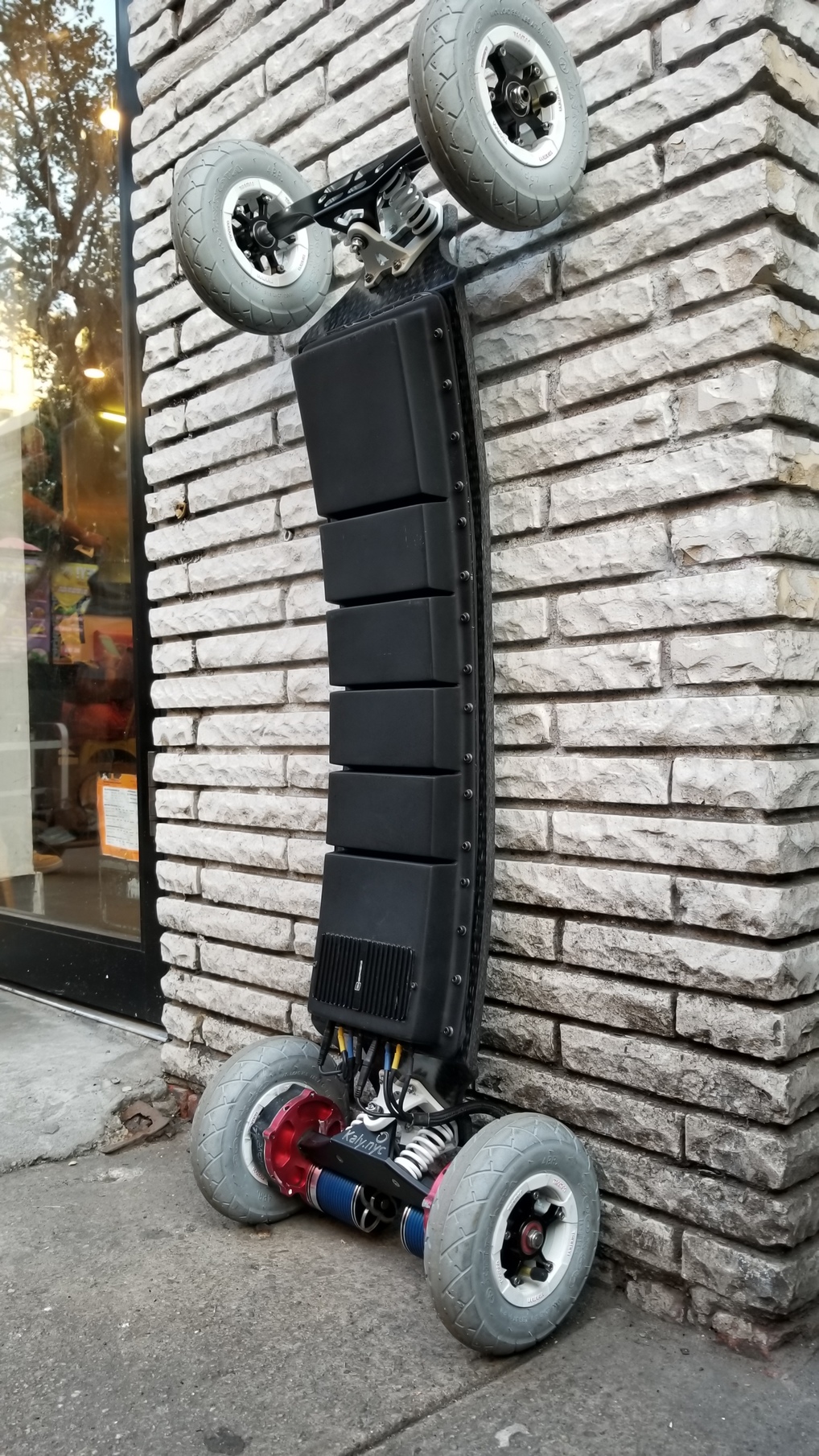

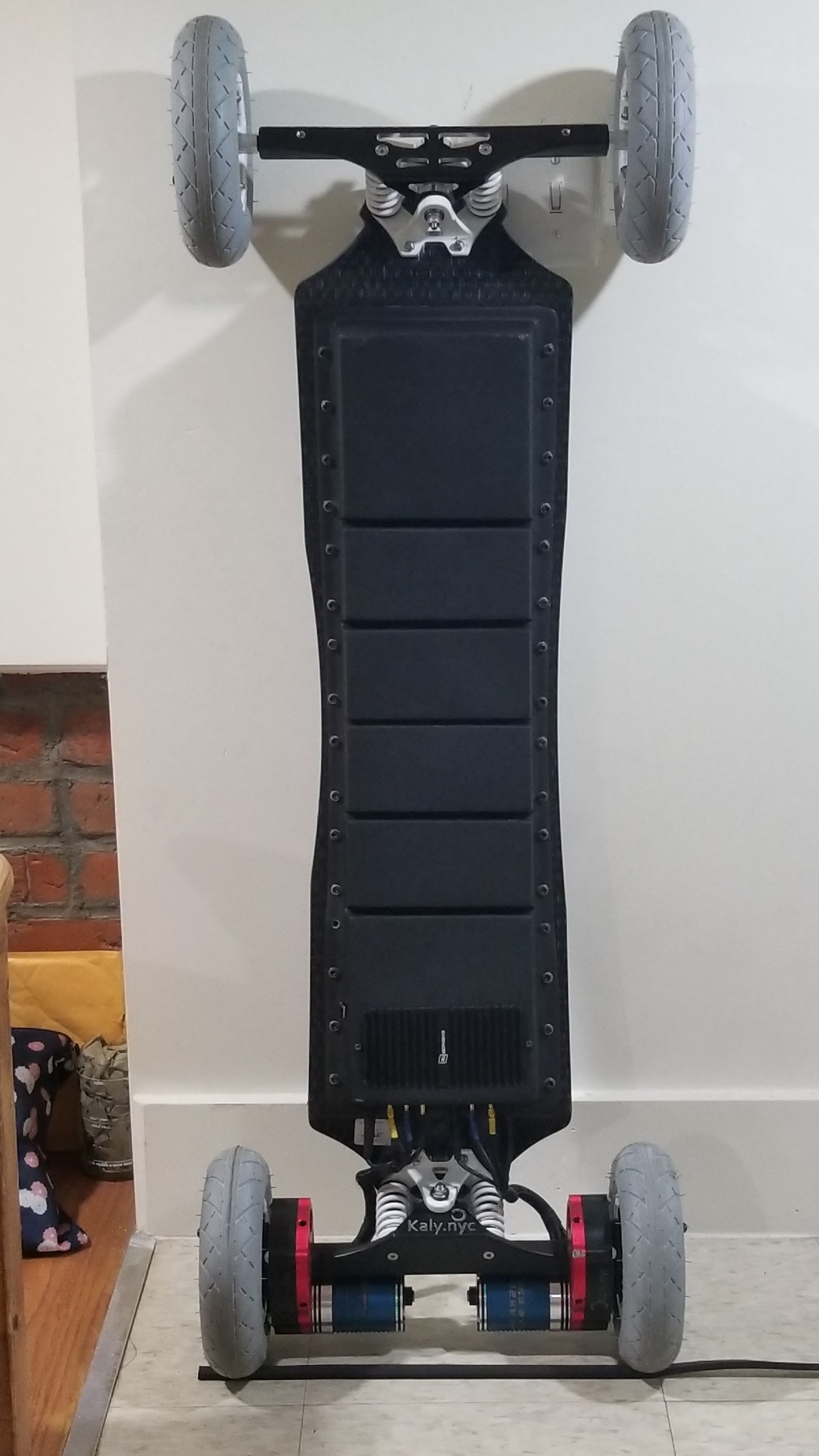


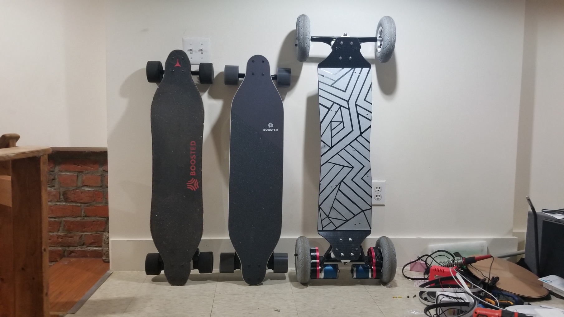
Oh you might also be wondering why I have a stealth in the last picture even though I’m building a DIY and I already have an existing v2. Well I won it for free a few weeks back from the boosted summer showdown contest.
That’s it! Thanks to everyone who made this build possible: @ARetardedPillow, @Kug3lis, @Kaly, @Eboosted, @Nate
22 Likes
This must be the best Trampa build ever, direct drives, an amazing work on the battery/enclosure and tons, TONS of AMPs! Congrats Neil must be the fastest board in town
Yeah, coming from a boosted, my body is not ready yet for this speed and acceleration. I was getting anxious when I was hitting the 30mph mark:

But damn, that was what, 70% duty cycle at 30mph? This thing can go so much faster if I had the balls to push it. In time, I guess. Plus I need to do something about the speed wobbles. Time to put on the dampas.
6 Likes
Take your time brother It really hurt to hit the ground at this speed
6 Likes