its a little bit big, but it does the job and its very affordable.
all of my other builds I have just had a deans connector to the battery that I simply unplug.
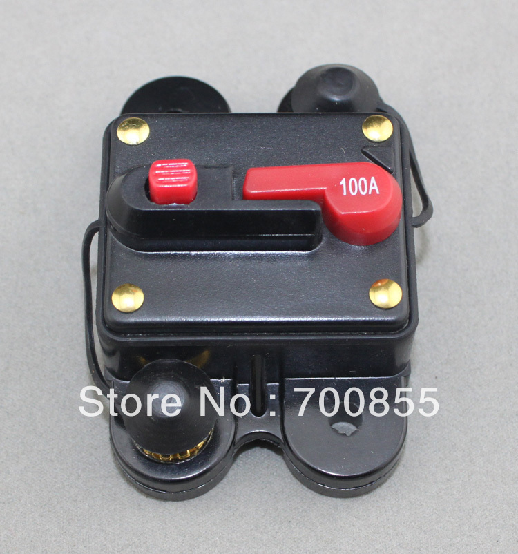
like this:
also on that latest build I wanted it to be a closed box with no wires to plug or un-plug with the exception of the battery charger. I wanted it to be “idiot proof” so to speak simple as possible so that anyone without any electronic knowledge could pick it up and use it without fear of exploding or something.
most power switches wont handle the high current inrush when you connect the batteries.
There are FET controlled solid state switches available but they are expensive and require power to work.
So the breaker seemed the most logical solution, and it also doubles as a safety feature, because… its a circuit breaker.
I’ve used a couple of these as well. They do wear out because of the internal spark, but if you use an XT90 antispark plug in line with it it will probably never wear out.
Hey, where did you fine those wheels and mounts that work with them? I’m having trouble finding pneumatics and parts that would fit with the larger wheels
This is my first build took a lot of time and mistakes to get it how I pictured it. (still room for improvement)
The battery is a 6s 5000mah (two 3s 5000mah connected in series) with a 40 amp bms for charging and discharging. The battery enclosure is PETG. Designed it myself (not a fan of my LCD placement, will change later) on the left is the charge port with a debris free cover and on the right is for my key/power. It is attached to the board with M5 bolts that thread into a metal insert that is flush with the board. Both enclosures also have TPU gaskets that go on to keep them water tight-ish.
The board is not flexible what so ever but already have plans to put everything on a bamboo deck once I design the enclosures.
I have the HGLRC-Flipsky FSESC 4.12 50A VESC which has also been very nice for me. would recommend if you find it on sale for BLDC setup. Will try FOC sometime in the future, need to do more reading on it. I used the VESC tool to help my setup the motor is running at around 40 amps and the VESC is running at 25 amps I believe
The motor is the tancon 245kv 63mm. So far has been bullet proof for me. Was wondering If I should install a cover for it or the air rushing around it is needed to keep it cool? Thanks
The motor mounted is a 3D printed out of PETG with two 3mm rods inserted in it. Have had to tighten it once since I installed it but I think that was due to breaking it in. Its been solid since then. I am waiting on a metal mount at the moment just couldn’t bare waiting any longer.
Wheels are 83mm and the “JK” logo was done in Photoshop with some mad copy and paste skills
Also the gasket under the back trucks was 3D printed so I could route the wires away from the motor. Works very well so far not even close to pinching.
Please feel free to leave questions or concerns you may have!!!
I would be happy to share the files for the enclosures, gaskets and riser if they interest you.