OK SO HERE’S MY BUILD THREAD This is my first ever eboard! So be nice!
I want to share my build process and ideas in the hope that it will contribute some useful info back into this fantastic forum, as well as showing that someone without any experience can build a fairly decent e-board.
I definitely could not of achieved this build without the huge amount of info submitted freely by others on this forum, so THANKS. I’m also open to & asking for feedback on my build, such as; possible improvements OR just PRAISE for a job well done! :lol:
I plan to write this Build Thread using as much detail as practicably possible. I will also break my Build Log into four parts in the hope that it makes it easier to read:
PART ONE: WHAT TOOLS DO YOU NEED TO BUILD AN E-BOARD
PART TWO: RESEARCHING & BUYING PARTS
PART THREE: BUILDING THE E-BOARD
PART FOUR: TESTING & REFINING THE BUILD
Before I get into each section I want to briefly talk about my thought process, specifically what led me to build an e-board vs buying one ‘off-the-shelf’. I had started to see more and more e-boards getting advertised online not to mention the few start-ups such as ‘boosted boards’ and after watching the TED TALK about it I was sold on the idea & I seriously thought about just buying one pre-built off the shelf or throwing in a pledge to the kickstater campaign to get a boosted board… I am really glad I didn’t…and seriously who has $1200+ spare?
So It must of been June or July-ish 2013, when I first saw Beetbocks holey truck mount! The moment I laid eyes on that thing I was super desperate to get my own electric powered skateboard but now the plan was to build-my-own electric powered skateboard. I started to read the 40+ page thread by Beetbocks and realised I had no idea what they where talking about… I knew I had a lot to learn about this stuff before I could ever build my own e-board…
Well several months later I have a working board and it is FUCKING AWESOME fun… So my advice to whoever is reading this who doesn’t have an e-board start planning now it’s not as hard as it might seem, YOU CAN DO IT!.
So Start planning your build today!
PART ONE: WHAT TOOLS DO YOU NEED TO BUILD AN E-BOARD
These are the tools I used during construction, you might not need all of them but probably most of them. Also at the bottom a list of useful materials that I used in the build
Cordless drill
Jigsaw
Dremel
Angle Grinder
Soldering Iron & Soldering Clamp / Assistant
Pop riveter
Socket Set
Allen keys
Screw Drivers
Rubber Mallet
Hammer
Ruler & Measuring Calipers
Multi-Grip
Needle Nose Pliers
Stanley knife
Cigarette Lighter
Metal file
Sander, Sand Paper
Decent Work bench
Sewing Machine
RANDOM MATERIALS I USED/NEEDED
3-4mm rubber sheeting
Aluminium Angle
Aluminium Flat Bar
Black Plastic Milk Crate (This was cut down and used to create the chassis which all the electrical components mounted onto)
Velcro (with self-adhesive backing & without)
Nylon Strapping
Washers of various sizes
Nuts & Bolts
Cable Ties
Super Glue / Loctite
Solder
I wanted to minimize the amount of stuff that I had to spend money on during the build, so I built the electrical components chassis mostly out of the spare parts & scrap that I had laying around the garage.
[size=150]PART TWO: RESEARCHING & BUYING PARTS[/size]
This stage for me was the most confusing, I am not familiar with RC parts and found it extremely difficult working out what I actually needed. Also I live in Australia so buying the stuff everyone else was using to build their e-boards was a bit more difficult but mostly more expensive (SHIPPING TO AUS IS FN EXPENSIVE)
but eventually everything fell into place when I read this post E-GO by Yuneec Internationl | Endless Sphere DIY EV Forum from ‘LOSTMD’ everything seemed to make a lot more sense and the task seemed achievable now I knew exactly what to buy! - I love when people just tell you what works!
THANKS LOSTMD
So originally I was going to buy the bare minimum an just build a SINGLE REAR DRIVE E-BOARD, this would be cheaper by several hundred dollars compared to the popular DUAL DRIVE OPTION (which is what I really wanted) However I was on a tight budget so would have to make do with a single motor!
At this stage I calculated that the parts I would need would Cost just over $700 delivered to AUS. I was happy with that.
AT THIS POINT A BIG THANKS GOES TO FORUM MEMBER JACOB! He sold me he’s spare alien parts (DUAL caliber mounts kits & motors) and that made things happen allot faster & cheaper than if I had to buy it all from overseas! thanks again Jacob.
YAY! - NOW I CAN BUILD A DUAL REAR DRIVE!
I also decided to Frankenstein my old-school freestyle deck to save about $100

So here are the parts I ended up with

[size=200]PART THREE: BUILDING THE E-BOARD
[/size]
NOTE:
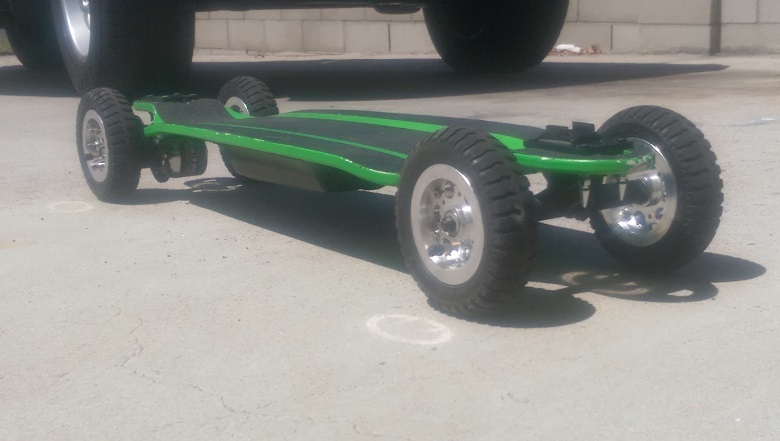
Its not a long board! IT WILL BE ONLY 29-INCHES WHEN COMPLETE
Trying to save money so used a deck I already had this saved about $100
Re-drilled the front truck bolt holes to push the truck to the front of deck (I also did this with the back trucks later to maximize wheel base)… this will give me some extra room for components and maybe improve stability! Looks tough too!
Cut some radical shapes into it to prevent WHEEL BITE!
Made an extra riser out of some 4mm rubber stuff (to add to the super slim ones I already had) hopefully to prevent WHEEL BITE! and maybe absorb some extra vibrations to give a super smooth ride!
At this stage I took it for a test ride today to see how the Caliber trucks perform on a small deck & to see if my radical deck modifications ‘feel’ ok…
THE SETUP FEELS PRETTY AWESOME… LOOKS FUNKY TOO… I also guess its rather lightweight compared to a long board… can you say “POWER TO WEIGHT RATIO”?
First thoughts after test ride - The bushings that come standard with the caliber trucks are very soft, probably great for a long board, but I weigh 90kgs and they are just too Juicy for this type of ‘short deck’. So I pulled some harder bushings from my other skateboards to see if i can tighten things up a bit. I got it pretty good but if I went any faster there would probably be problems with the ride quality…
So I ordered some VENOM SHR ELIMINATOR BUSHINGS 94a $17ea from Boardshop.com.au (free shipping). I didn’t want to spend the money but I also know that having the right setup is super important especially if you are planning to go fast-ish. Anyway I read somewhere these bushings are meant to be pretty good, so well see how they go with my setup. I Personally like my boards to be fairly stiff and this deck allows for lots of foot leverage (huge kick) which helps to steer when you have tight trucks & hard bushings, which is what I am trying to achieve.
The ABEC 11 Flywheels I have are 83mm @ 75a (they are huge but awesome - biggest wheels :shock: I have ever had!). They are super soft and feel great under foot, should be very comfortable cruising at high speeds. NOTE: very slippy in the wet! pulling some awesome 4 wheel power slides today after the rain stopped!.
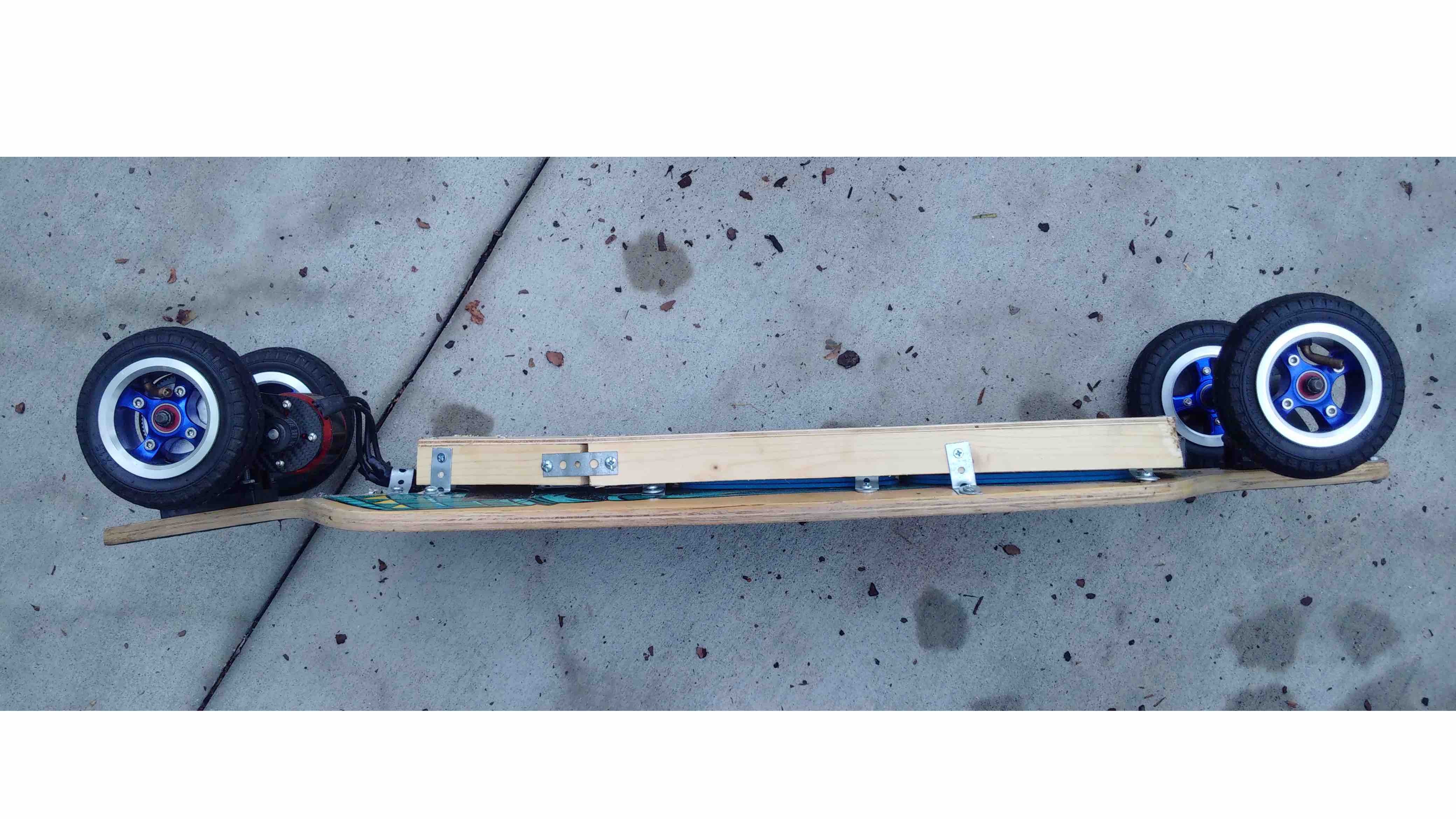
[size=150]PHOTOS OF MY BUILD BEFORE MY ELECTRONICS ARRIVE[/size]

[size=150]PHOTOS OF MY BUILD AFTER SOME ELECTRONICS ARRIVE[/size]
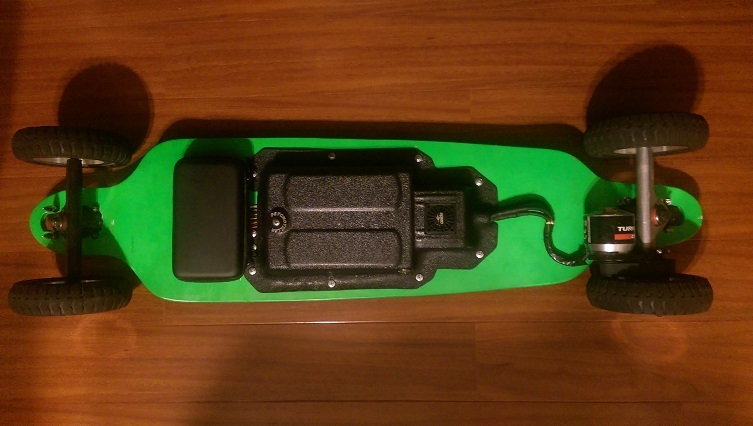
Made some good progress thanks to JACOB! I Didn’t have to wait weeks for parts to arrive and now I have Mounted dual rear NTM Prop Drive 50-60 270KV / 2400W! FN awesome!
Its going to be crazy on this board… very short board 74CM (29INCH)
I also slightly modified the deck (again), I cut the huge kick down, it was JUST TOO HUGE! I realized after riding the board around the streets that it was just not perfectly balanced & probably going to be a problem during acceleration as it was way to easy to accidentally put your foot weight down on the huge kick and POP mono’s. MONO + ELECTRO POWER BOOST = BAD. It also gave me way too much leverage over the trucks which made wheel bite more likely (even with the super hard bushings)… Also I pushed the rear trucks further back hopefully to improve overall stability & handling.
PROGRESS PHOTOS


[size=150]FOR THOSE WHO ARE WONDERING, CAN THOSE MOTORS ACTUALLY FIT SIDE-BY-SIDE? YES THEY CAN!! [/size]
NOTE: I had to put 3 extra axle washers on each side of the truck to provide the extra space. So this is a total of 4 axle washers each side sitting between the inside bearing and the hanger. This resulted in a 1mm gap between the motors.
I think the washers are about 0.5mm thick.

[size=150]PHOTOS OF MY BUILD AFTER THE REMAINDER OF MY ELECTRONICS ARRIVE[/size]
When it came to wiring this together I basically copied beetbocks setup… This still actually took many hours to complete, I was a bit nervous and really never done anything like this before, basically I didn’t want to screw it up so worked very methodically!
SOME TIPS / FACTS
I used heat shrink tube stuff on all my wires & solder joints and made sure I used ASS LOADs of solder so everything was strong! I don’t want to pull it apart
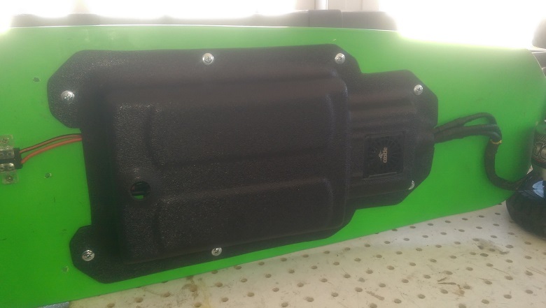
I didn’t want the hassle of needing to remove the battery to charge so I tried to design the chassis to have the necessary connectors fixed in place & easily accessible
The black plastic thing - that the battery is strapped to is actually made from a BLACK PLASTIC MILK CRATE
… it just so happened that the side panel of the Milk Crate had the perfect dimensions for the battery to sit inside, it is also made out of very strong - nearly unbreakable plastic, however was really easy to work with!
I also tried my hardest to make it look really neat & semi-professional??? I personally don’t like wires all over the place and because this deck is tiny so I had to JAM everything into a neat small package!
So I built a raised platform (out of milk crate plastic & various aluminium profiles) to mount the ESC, this created an area underneath where all the excess cables can be positioned and where I mounted the momentary switch for the anti-spark & also the xt90 for the kill switch & on the otherside the xt60 for charging the battery.
The ESC is held in place with stainless steel pipe clamps that i had laying around
Notice the Leads from each motor are crossing each other and connecting to the opposite side of the ESC, this seems to work out the best as the wires that come from the motors are really stiff and naturally where heading across to the other side of the ESC, therefore I let them sit the way they naturally wanted and connecting them to that opposite side, this is also allowing slightly longer wires (which are nice & flexible) to come out of the ESC. - Having the wires positioned in this way they don’t restrict the truck movement.

PART FOUR: TESTING & REFINING THE BUILD
So after months of research & waiting & building I got to go on my FIRST RIDE! sooo much fun!
I played around in the street testing firstly so I could easily head back inside to the computer to program in any changes I wanted to make in the ESC software.
This is what i have configured currently it seems good for me.

So I figured I should go for a ride to the bottle shop & get some beer!
On my way home a funny noise was coming from my board… mmmm
So looks like I lost some motor screws! DAMM IT!
HOT TIP: Use Loctite!
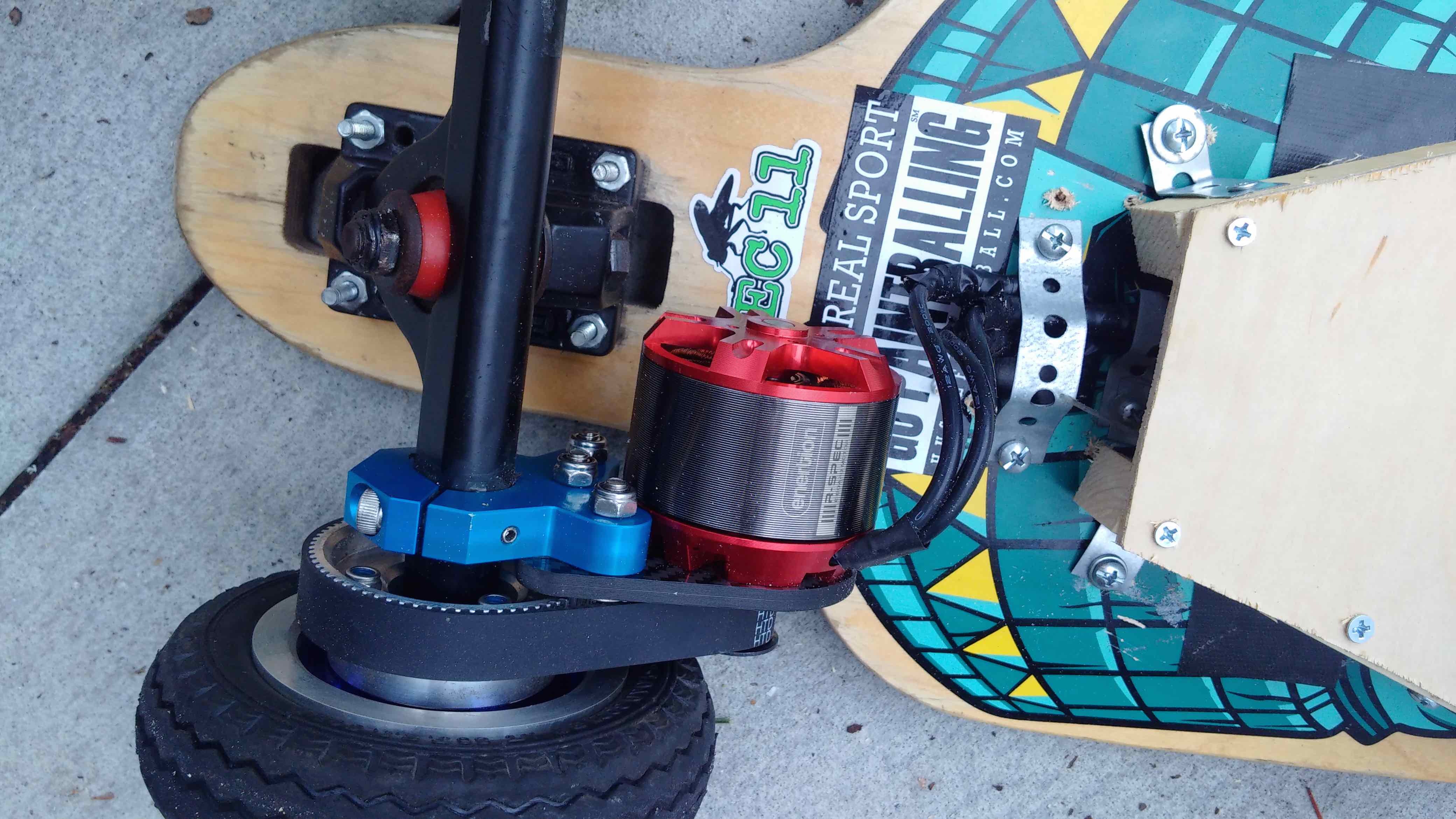
But the other thing I noticed was that the caliber mount was also moving/swaying (at the motor end) just slightly, 1-2mm from left to right when forced. This is a MAJOR problem for me because I don’t really have any room for movement in my setup! I could actually see that the wheel pulley had made contact with a motor mount screw…
This picture is for illustration purpose only - so you can better understand the movement I am trying to explain

So after I walked home, with three screws less then I started with and a clamp that was striking against the screw I realized I needed to do a bit more work!
Firstly I tried to tighten the caliber mount to prevent it moving, but I nearly broke the allen key… It was super tight already! but there was still a slight amount of ‘play’ this meant that when the motor was pulling hard during acceleration (or maybe braking) the caliber mount became slightly misaligned
I also assume this slight movement might also add unwanted vibration or some other unknown problems might occur because of it…
SO WHAT TO DO?
Firstly I put loctite onto all the motor screws & pulley grub screw and they haven’t’t budged
I also made up two cross braces using some threaded rod and some other bits-n-pieces
I bought some longer stainless steel bracket screws that screw through the entire width of the Alien Caliber Mount plus about 10mm more on the inside, therefore allowing me to screw directly into the ends of the cross braces as they have the same 4.0mm thread on each end.
So this is what I came up with to ‘brace’ the caliber mounts and totally eliminate all movement - THE MOUNTS ARE ROCK SOLID NOW -