It’s my opinion that this should be handled by the BMS and not an add-on circuit. The balancing circuitry in the BMS would be best suited for this, maybe have a place for a large resistor or energy sink to hook up. @SimosMCmuffin
Thank s for the replies guys. Yep à BMS managing this would be killer (was thinking of the FLEXIBMS) ; still would be nice to get a spare pcb to simply hook up to your battery?
Even at only 20w, those 100w resistors get burning hot in seconds. So hot they burnt the piece of wood they were mounted too. You’ll need a lot more than just one, hook them up to a large heatsink, and probably still need a fan (a big fan).
Generally think the issue with this idea is finding something that can absorb the load. 225w is only like an extra 6a of breaking power…
Mellow has this in a 1000w resistor…inside a tube of aluminum…
If it’s built right, it’s only braking power. If it’s built wrong, it might be breaking power.
Heh, I just googled this and ended up right back here. There’s also some info on their website.
I’d be interested to see this, all the big resistors (1000w range) I came across were huge, as in the size of my forearm. Anyone pulled apart a Mellow board?
edit… Nevermind they have a rundown on their site too.

I’m not suggesting that a 100w resistor could effectively bring you to a dead stop. I watched the video, and based on that use case (light, short braking) a 100w resistor would be fine.
I know how hot they can get. We used to use them to make heated beds for repraps back in the day.
Well, that should do!

I suppose it could be done on the Switch-module. I don’t see any real reason it couldn’t. Might be actually possible to just use the BQ76200’s Charge FET output to directly control a N-channel FET going to a brake resistor. Heat dissipation might be the real problem, as you need to dissipate all that extra power somewhere else than the battery.
Heat dissipation wouldn’t be the BMS’s problem ![]()
If you want to hook up an external dissipator though, it’d be interesting if the BMS had a spot for it. Maybe even a power resistor bolted to the truck hanger or something, dissipate heat on that…
I was about to ask about the type of resistor you’re thinking to use. My first thought was something located on the switch PCBs itself, but you seem to be thinking of a completely external resistor. I suppose the easiest could be to just leave wire hookup points available on the board.
As we can see above, it may not even be a resistor. I wouldn’t assume what it is at all. Just somewhere to dump energy, if it’s hooked up…
It’s always kind of resistor
About the discussion above between 100-1000W rated resistors, those are the continuous rated power under sufficient cooling conditions. A 100W resistor will burn itself out from the inside if it’s subjected to for example 200W for long enough time, because it simply can’t move the heat from the resistive element inside to the heat mass outside efficienctly enough.
But the resistor itself doesn’t need to be that huge, but rather have good heat transferring capability to a heat mass, which is preferably cooled. I believe Mellow is using their whole drive unit as a heatsink.
Could be a MOSFET run in the ohmic region as well. Behaves like a adjustable resistor, so the braking power can be controlled.
Could be a resistor, a diode, a light, a heating element, another battery, a supercapacitor, a motor & propeller
Never assume ![]()
Actualy you just assumed those components have no resistance 
But talking about supercaps, yesterday I bought mini screwdriver that has 4.6V 320F cap inside. It’s roughly 400mAh if my calculations are correct but pretty large charger that’s in a set charges it within 60 seconds. Also I don’t know how much of this energy can be used but I suppose that it might be more than in battery where you have to care about not destroying internal chemistry.
At what nominal voltage?
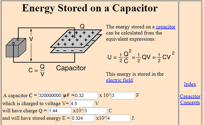
Capacitor stored energy: E = 0.5 * C * U^2 = 3240 Ws or J, if charged to 4.5V 3240 Ws = 0.9 Wh Li-ion equivalent capacity, using nominal 3.6 V → 0.9 Wh / 3.6V = 250 mAh
I used formula I found on arduino forum: 320F 4.6V capacitor can store Q=CV=1472 Coulombs of charge, 1mAh is 0.001 Columbs per second (0.001A) multiplied by 3600 seconds or 3.6 Coulombs. So the capacitor should be equivalent to 1472/3.6 = 409mAh
I’m talking about the stored energy inside the cap, which we can then compare to a li-ion cells nominal voltage capacity.
http://hyperphysics.phy-astr.gsu.edu/hbase/electric/capeng.html
Anyhow, how does the driver feel? How much can you do before the voltage drops too low?
