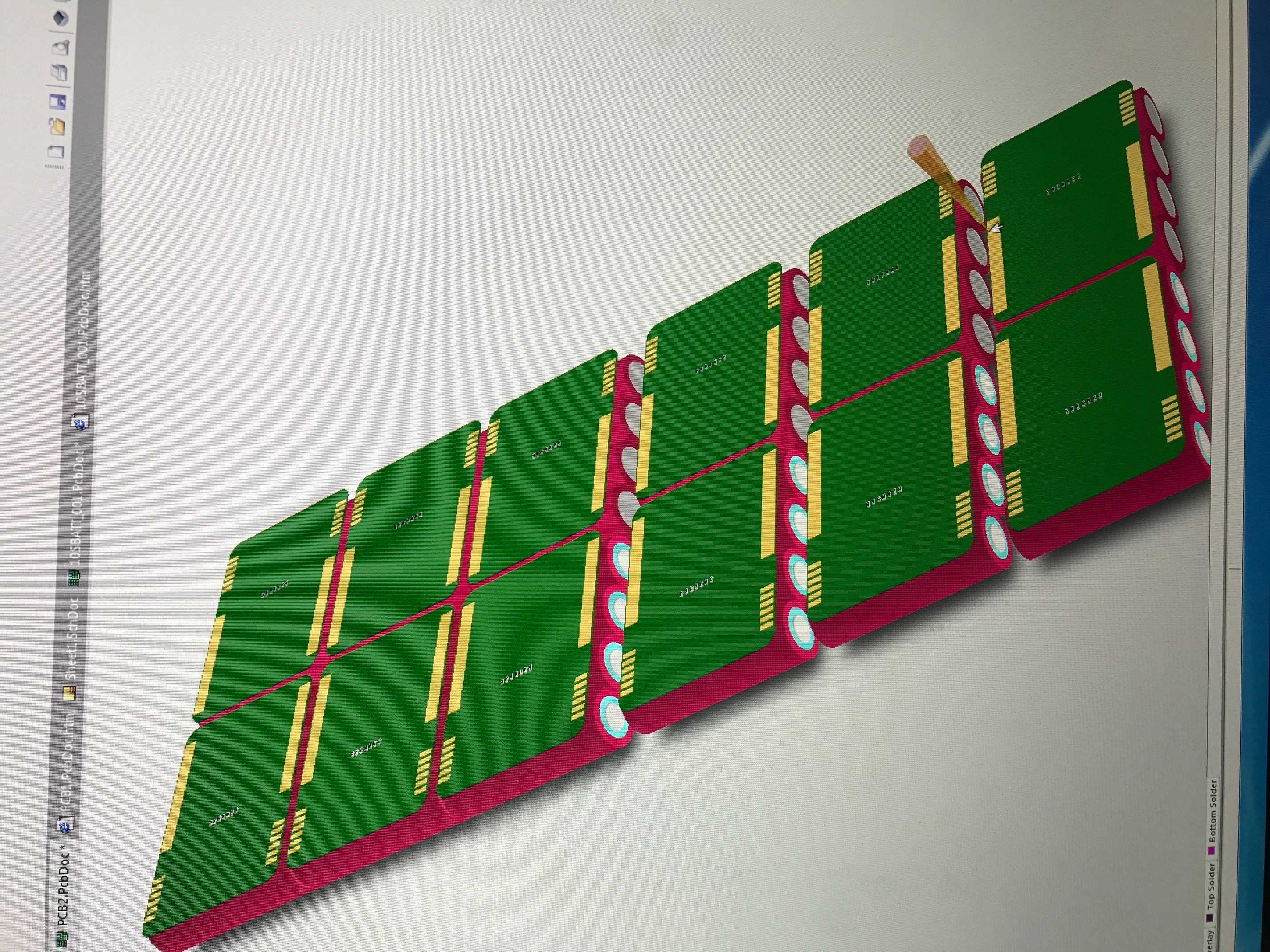
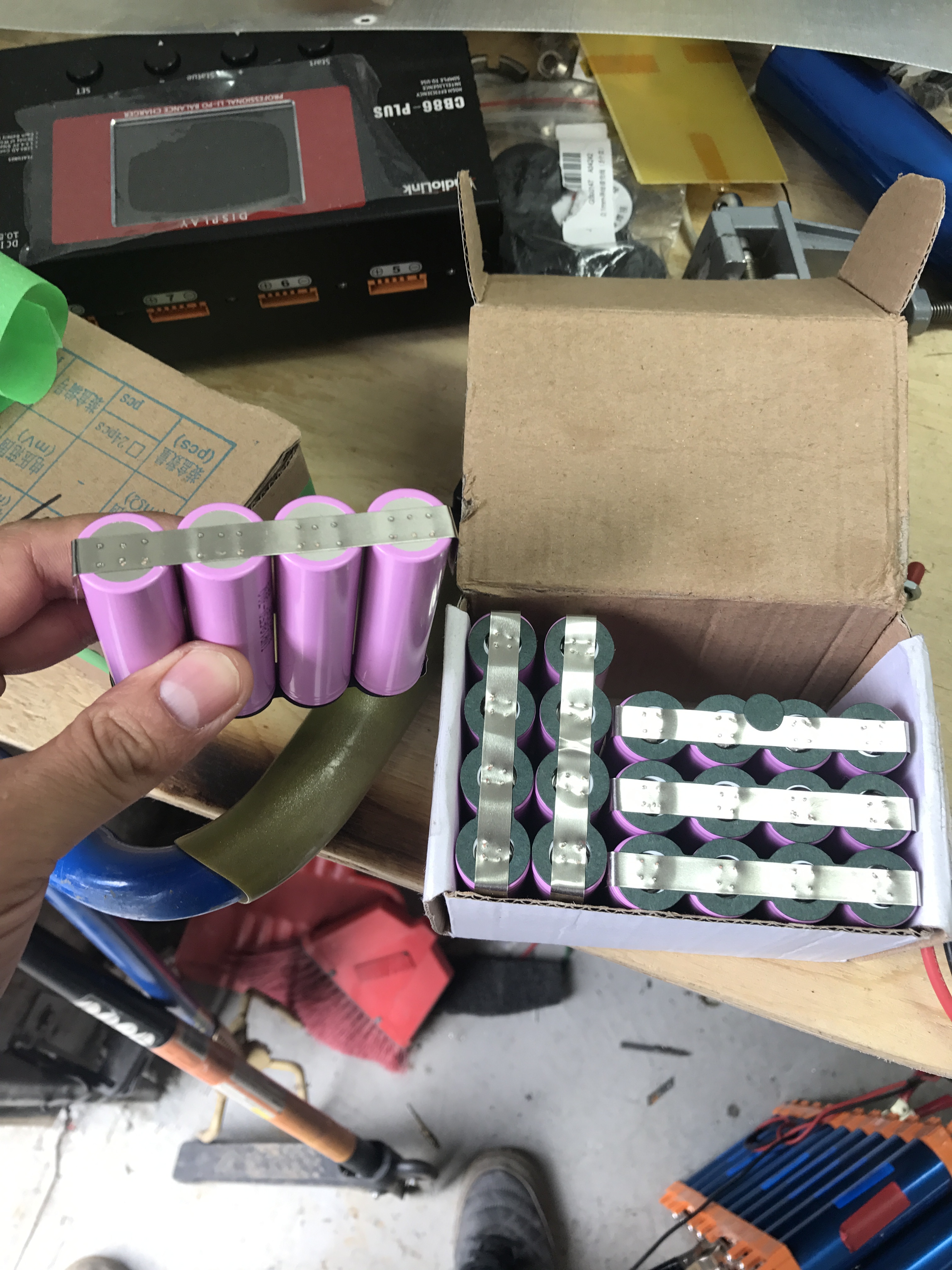
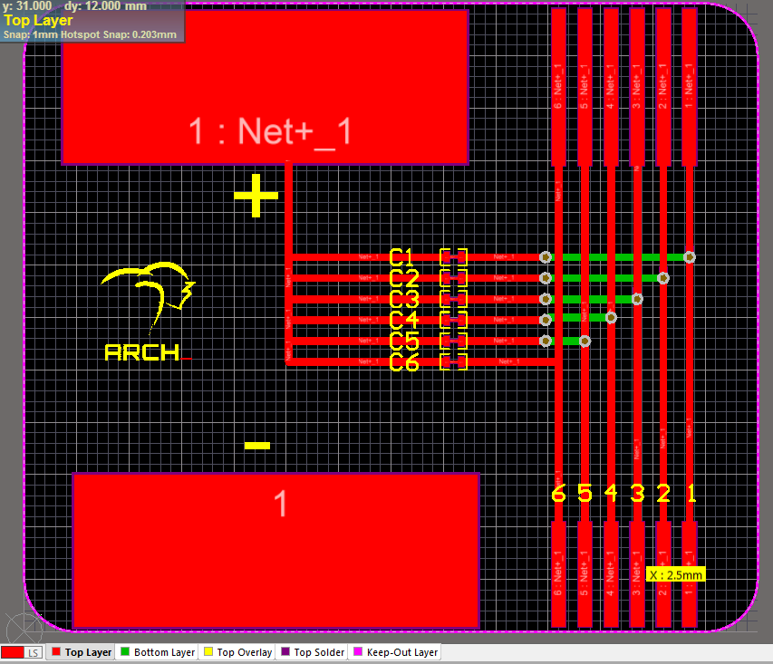
so we’ll be using a pcb over the top of each // pack, each // pack is spot welded together then soldered on to the pcb. Then each series connection is done from pcb to pcb. Then of course, the sensor wires are bussed down in a nice straigth line.
@Blasto@Arch thank you guys. I keep coming back to this thread every few weeks, and although sparse on words, there’s so much nuance and detail. I’m comparing to the other pcb designs, and this is what I’m picking up on this round of examination.
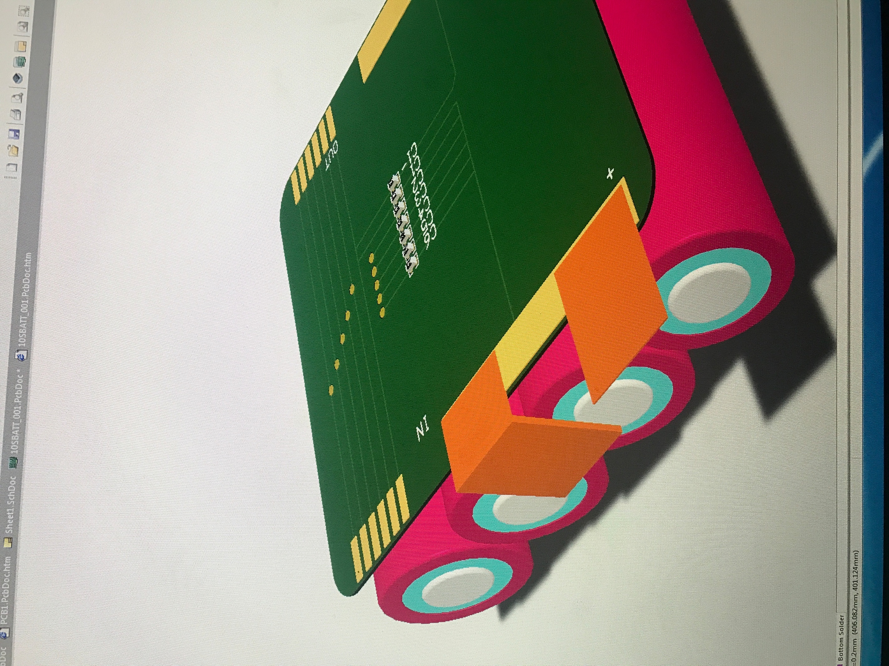
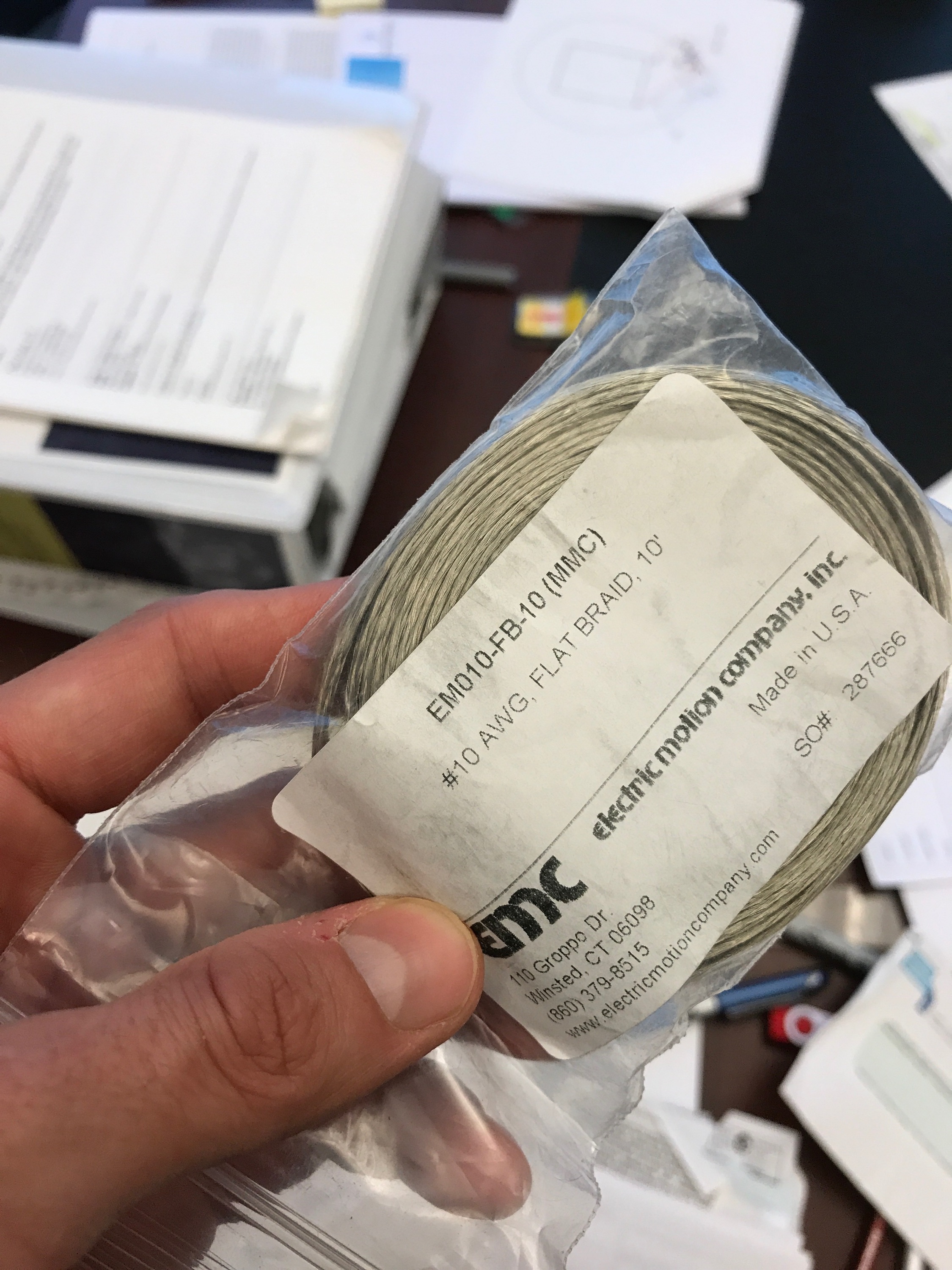
actual 10awg flat braid wire, not grounding strips of whatever diameter that should be 10awg equivalent
The connection between cells and PCB not nickel strip. It’s 10awg flat braid, presumably soldered to the nickel on the cells. Because using 10awg instead of nickel for this connection, the fact that the high current contact does not extend to the 4th cell does not matter.
but there is actually some soldering that heats up the cells. Unless the 10awg was soldered on before spot welding.
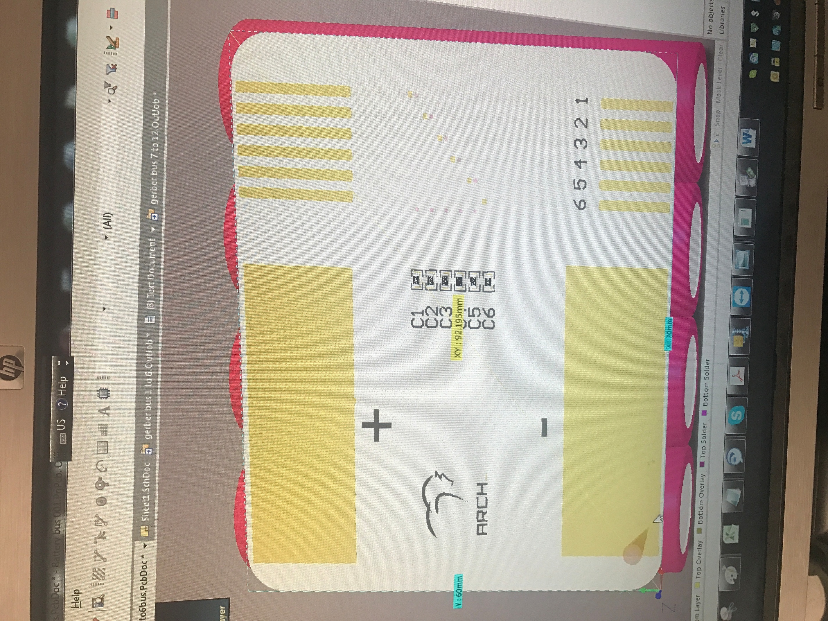
there are 2 different pcbs! the difference is the silk screening, 1-6s and 7-12s.
pcbway is actually really really cheap for this?
2 questions.
Can you share the pcb files? It’d be nice to have the link in this thread. I understand if not. This would be a fun thing to learn anyway.
Do you remember what you used for the ribbon cable?
The cells were spot welded in groups of 4 with nickel strip, then glued on the pcb. used the 10AWG flat braid to bring the high current path on the PCB (soldered on the top of the nickel strip, I have a good iron, took less than a second of heat)
yes, 2 reasons, to make it look peeerdy and with pcbway, a single design under 10X10cm is 5$ for 10 pieces (20$ for 20 pieces) so i had to justify sending 2 “different” design so i would end up getting both for 10$ for 20 pieces
TBH, i was not 100% satisfied with the design, too much track cutting and it was somewhat labour intensive. I would not feel comfortable with sharing a design that I am not ready to back up.
Besides, there’s a few guys that got inspired by this thread and that are selling their pcbs.
Thanks for responding. There are a few outstanding forum members who really know their shit. And people who really know their shit are bothered by the little things, the subtleties, learned through years of agonizing over the details.
Okay enough fluffing. What didn’t you like?
Sorry for being noob, this means cutting on the pcb with a knife? The photos look so good. What was it?
This means 1 oz copper, right? Is it enough for 4 x 30q worth of current, potentially 80a? I know the wires are almost touching on the pad.
the “cell” selection is done by cutting the pcb track, i debated by doing this or using a zeros ohm resistor. turns out it was more a pita to cut the track i did not want than to use a zeros resistor. It’s a very small cut, barely visible.
yeah 1oz is more than enough, by soldering the flat braid to the pcb and tinning, it’s adding a lot of “weight” to the pcb. Also, the flat braids is very close to each other, so the pcb is carrying the current for 1 or 2mm (engorged with solder)