All terrain flat deck | Loaded Fattail Deck | MBS Matrix Pro ii trucks | MBS wheels | Dual Ollin 170kv | Custom mount | 8S | VESC

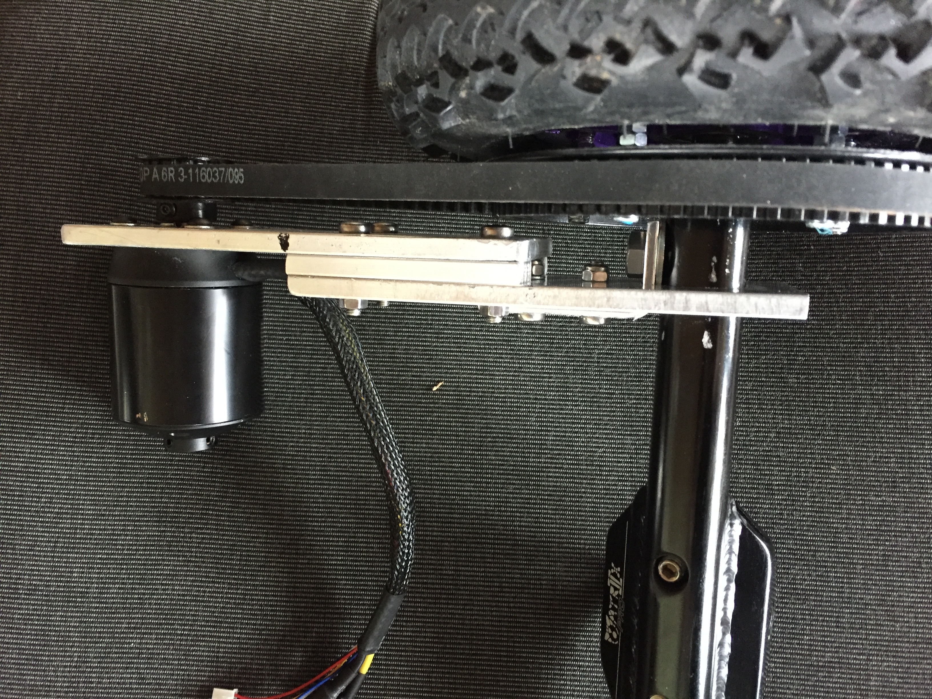
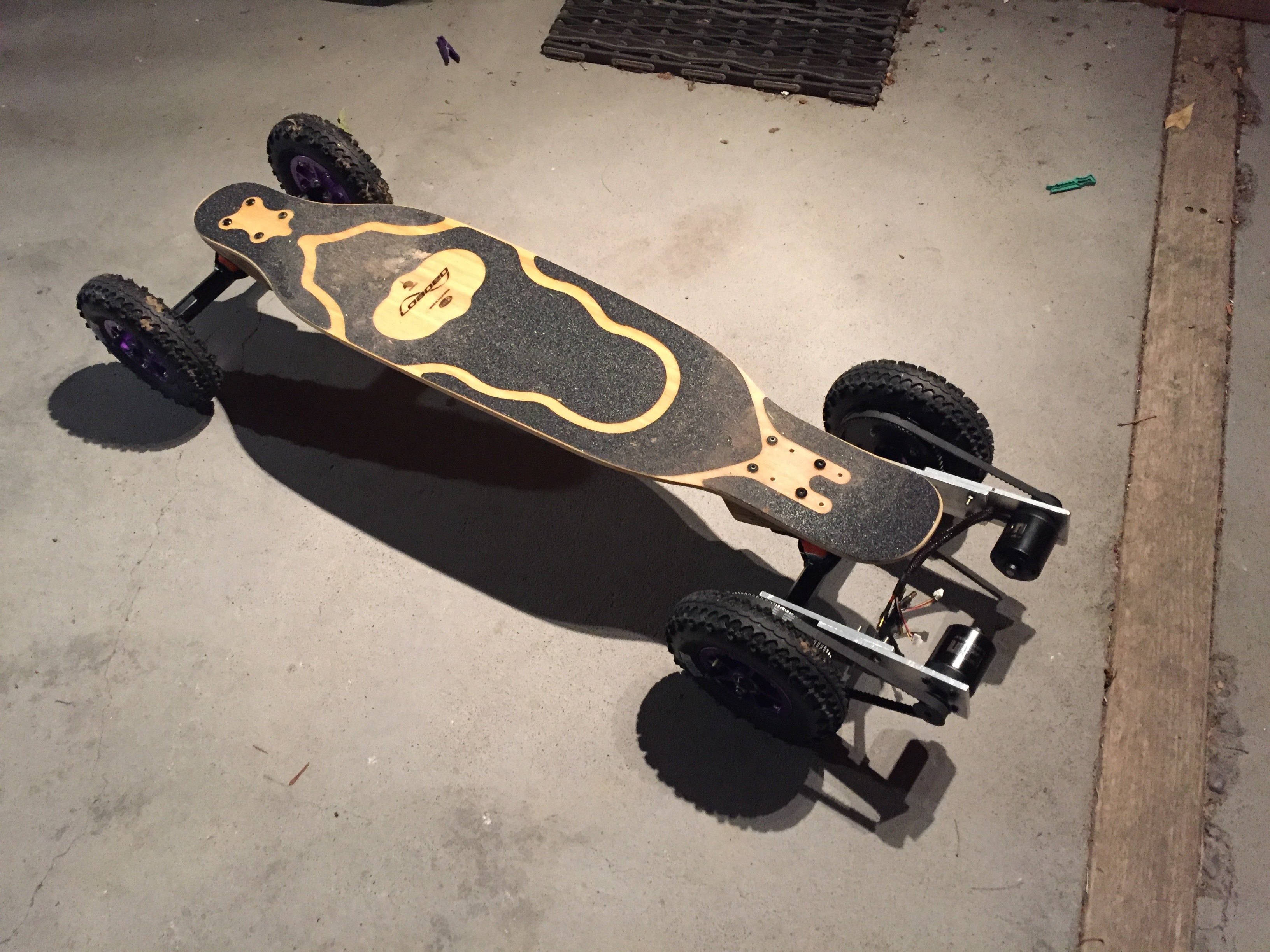
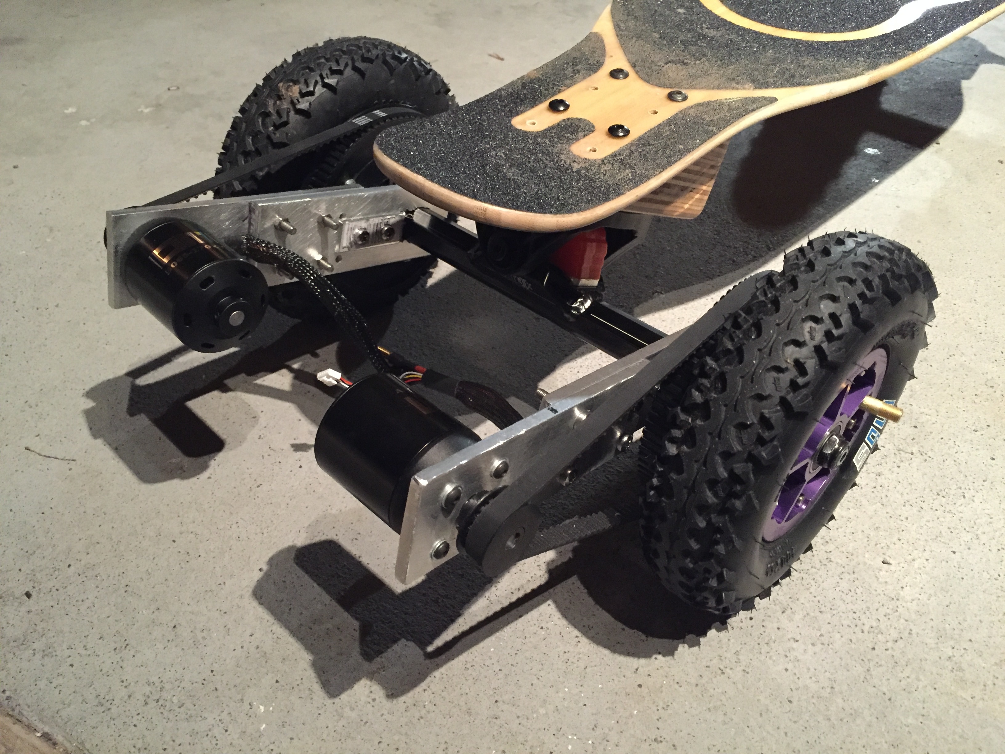
EDIT: Here are a couple of pics of the final build, turned out awesome :slight_smile:

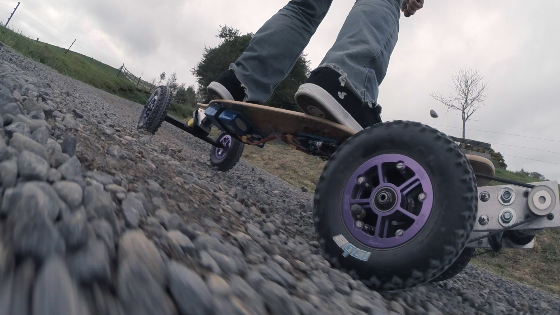
I’m new here, Hi! I thought it might be interesting to share my first build as it goes. I live in rural New Zealand, so wanted a board that was good off-road, but more for a cruise by the river with my kids on their bikes, rather than a full on mountain-board. I’ve not done very much skating, so a lot of this is unfamiliar, but I surf and snowboard so can handle riding a board. And I’ve built and flown a bunch of quadcopters, the electrics are similar.

So when I looked into just buying an electric skateboard, the Evolve Bamboo GT was looking about right. Only problem is, it’s not out yet, and they don’t even ship to New Zealand. So screw em, I’ll build my own!

First up was deciding the deck/trucks/wheels, and I’ve just now got that all together. It’s looking like this

I went with MBS wheels and (Matrix ii pro) trucks, the options for offroad wheels and trucks are pretty limited as far as I could find, and these looked the best. The mountainboard trucks made things a bit tricky, mountainboards have a tilted deck where the trucks are mounted, and I hadn’t considered how that would screw up turning with a flat deck. So I had to build some sort of wedge to rotate the trucks out by ~30-40 degrees.

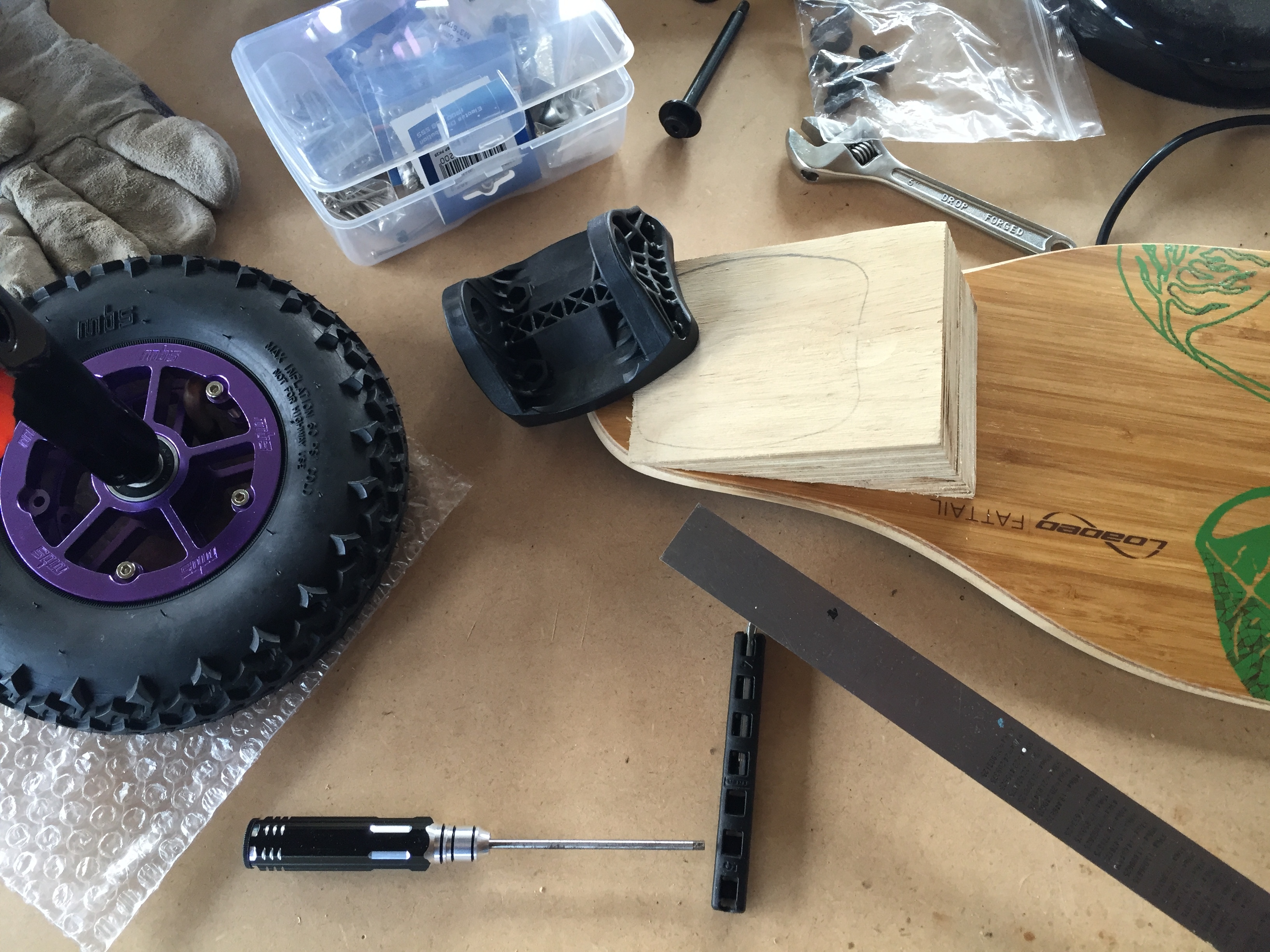
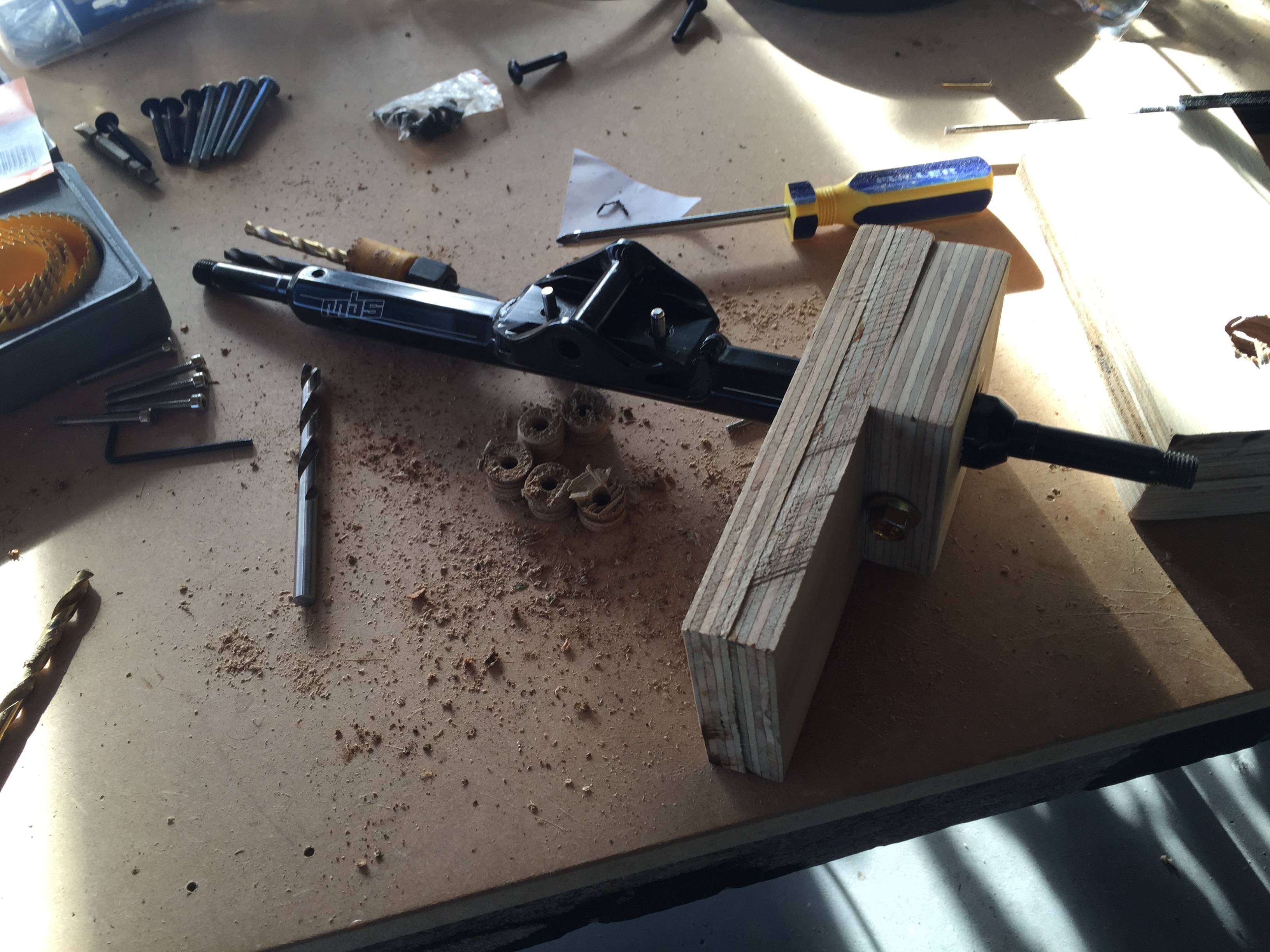
The simplest easiest thing I came up with was to use plywood. I got a half sheet of 12mm ply, cut it into a few smaller pieces, and glued it together with contact adhesive into a 6 thick 72mm brick. I then cut it diagonally with a hand saw which gave me the two wedges. I hand drilled holes for the trucks first, I needed to buy a few longer M5 bolts, and get a bit creative with the drilling. Then I drilled holes to mount to the deck, didn’t worry about nuts for that, just drilled long 4.5mm holes and screwed the M5 bolts in.

I chose the loaded fattail deck because I liked the design and I thought the shape might work OK with the wheels. Not sure if that will turn out to be a good choice, but I do love the deck. It has loads of flex which I love, but it might snap? Dunno.

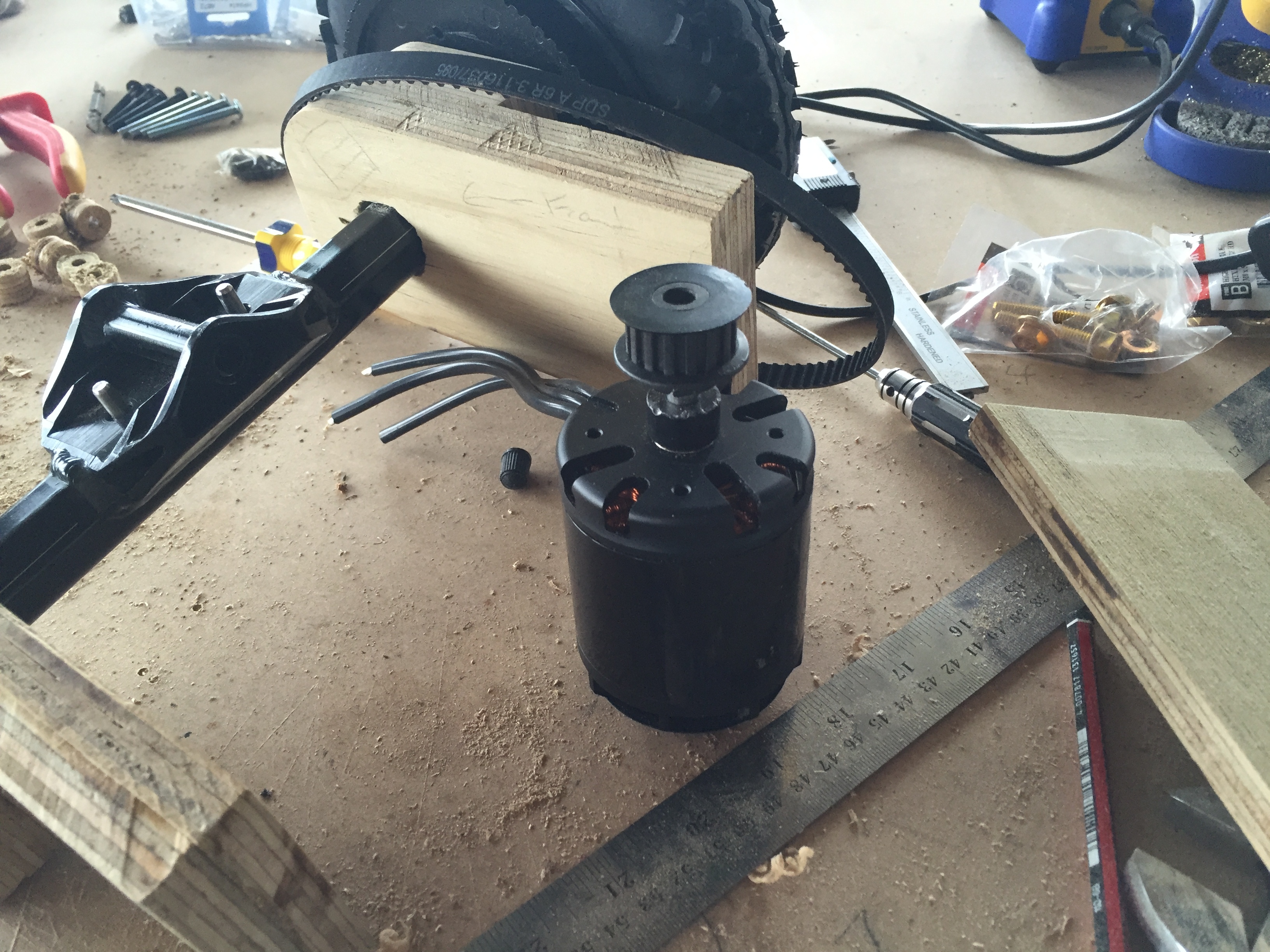
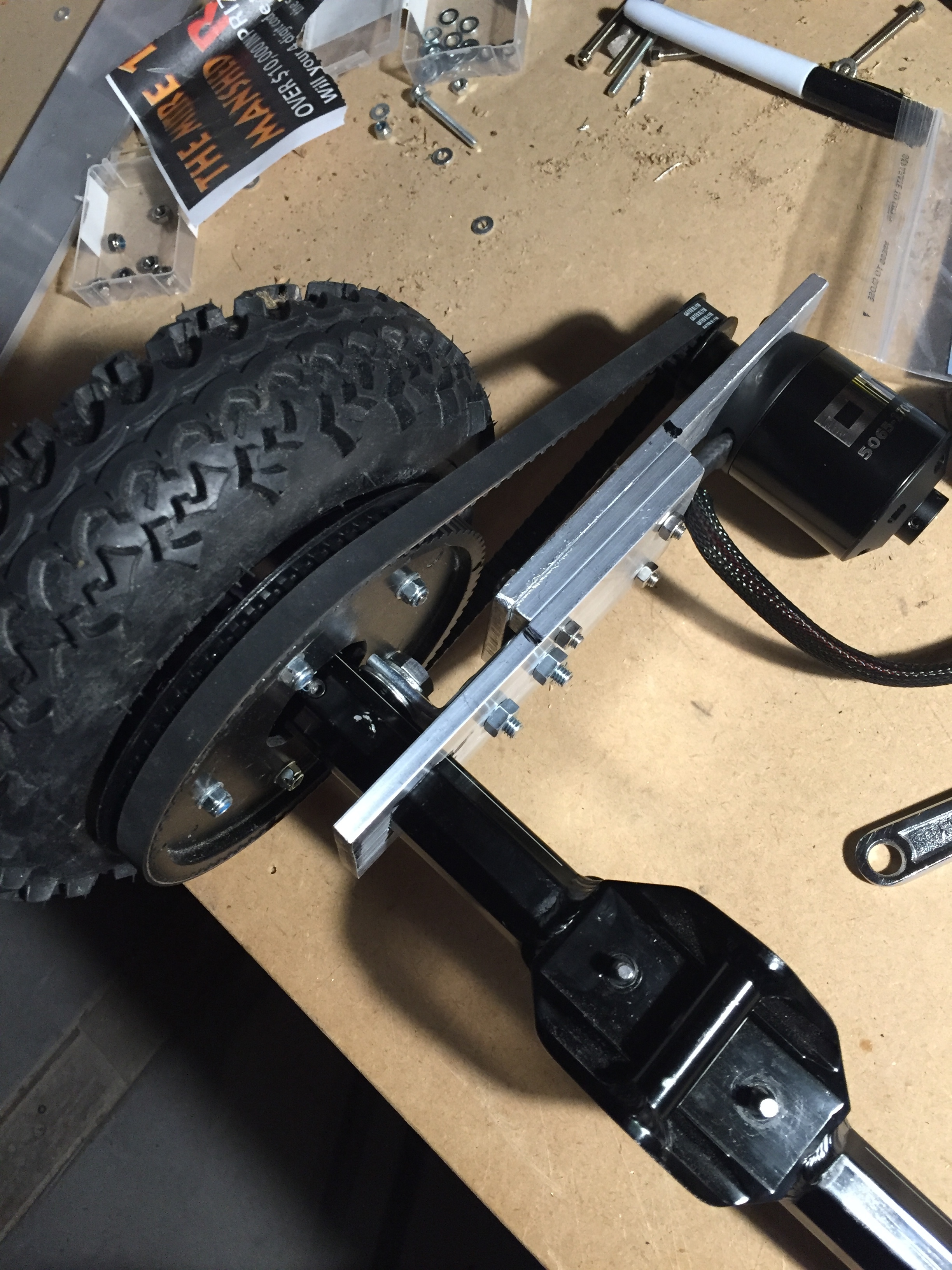
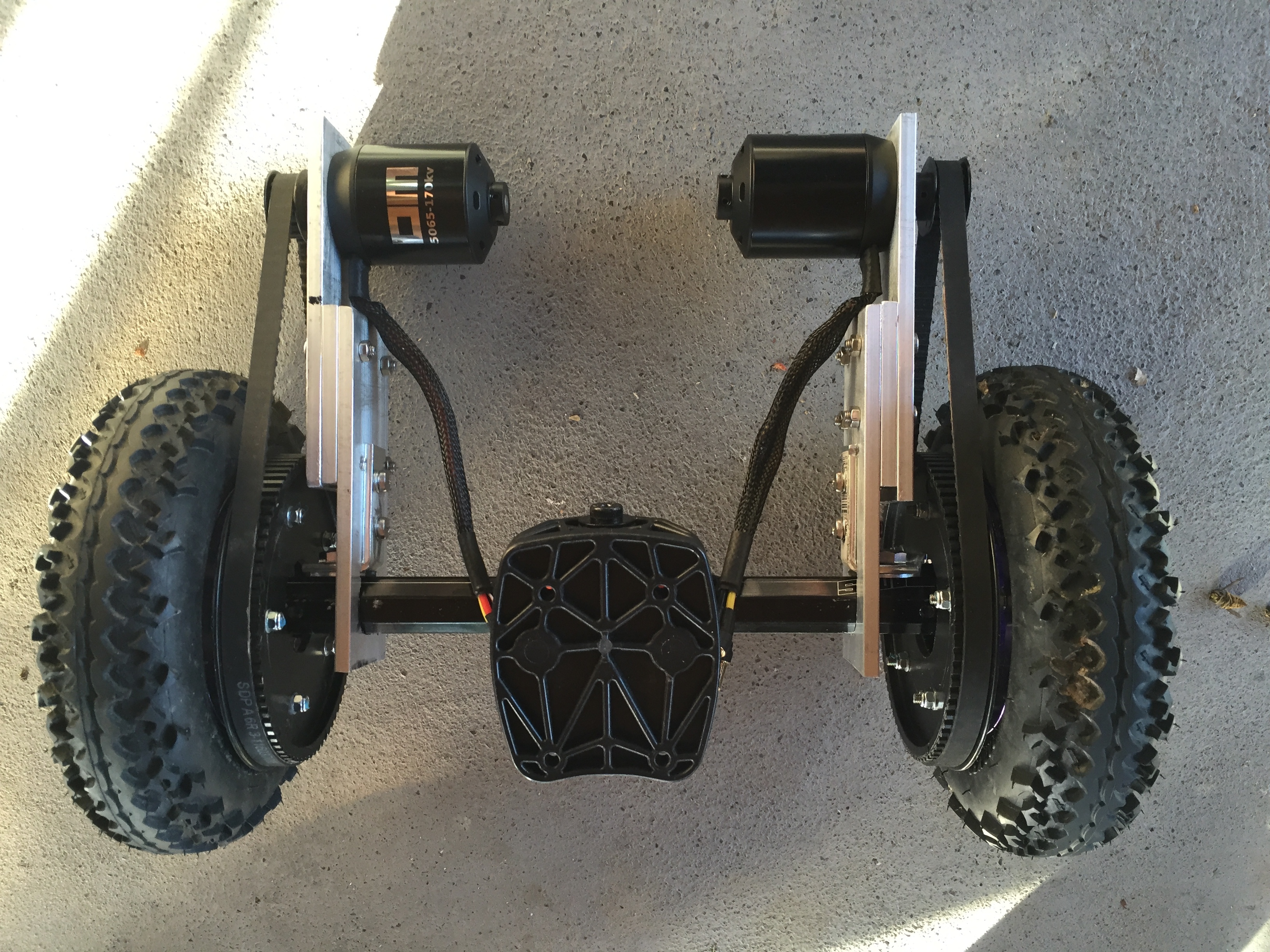
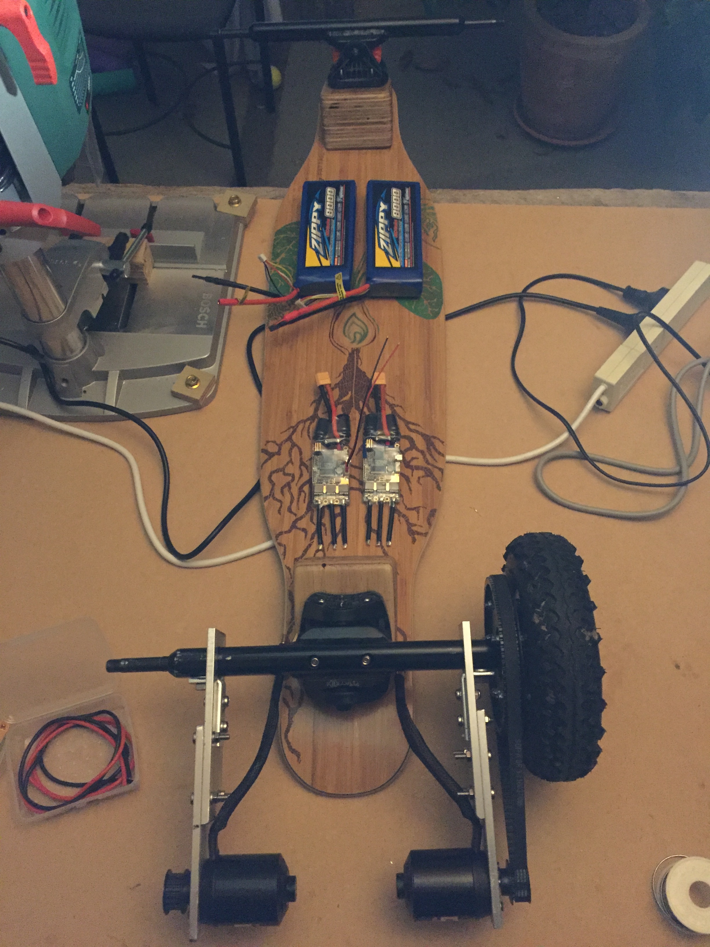
Next up (once I’ve had a bunch of fun just riding this thing down bumpy hills) is to build the motor mount. I plan to use ply for that too. I’ve already got pulleys and belts, that was hard for these big wheels! I eventually found a combo that seemed OK. It’s all plastic, might wear quickly, belt isn’t really what I wanted, but easy to work with, and in stock. 78T big pulley, 16T little, using a 9.5mm XL belt and I’ve got the emax GT 5345 170kv motors (EDIT/SPOILER I broke one of these later, went with Ollin 170kv motors instead), Enertion VESCS and will be going 8S LiPo, maybe 12S.

Any of this stuff might fail, and I’ll no doubt end up making everything out of aluminium not plywood, like mostly everyone seems to, but for now I’m just enjoying giving it a go. Fun times!

13 Likes

Build looks great so far! If you don’t mind me asking, where did you purchase the pully system from?

SDP-SI.com, this was the 78T pulley https://shop.sdp-si.com/catalog/product/?id=A_6L_3M78SF09510 they showed up fast, and they have a good range.

1 Like

I started work on attaching the pulleys today. The MBS hubs come with 5 M4x35 bolts connecting the two sides together, so longer hub bolts should work for attaching the pulleys. I drilled out the inner core of the pulleys, just large enough to avoid touching the trucks. Did it by drilling a bunch of small holes, some cutters and sandpaper. Then drilled the 5 bolt holes. Getting exact locations for the holes was a bit tricky with my limited expertise, and I knew I had to get this as perfect as possible. I used digital calipers to measure everything up, and scrape the hole radius on.

My M4x50 bolts are too short, the bolt that’s in there is only just screwed on at the other end, and the pulley is touching the wheel. I sort of knew that would be the case, 50mm was all I could find locally. I have some 60mm ones on order that should be perfect. I’m using a bunch of nuts as spacers between the pulley and hub, can’t seem to find a source for 10-20mm M4 spacers.

I decided to tidy up the plywood wedges a little, round off the edges and give them a coat of varnish, mostly for water/damage protection.

I’ve also been thinking a lot about the motor mounts, think I have a good design that will be strong enough just made with plywood, though I’ve ordered an aluminium bar, in case plywood doesn’t work out. It turns out that the MBS Matrix trucks have an M8 threaded hole in them in a pretty perfect place to bolt on a motor mount, so that’s going to be a huge help.

I’m a little worried about the XL belt/pulley thread still, haven’t seen much on how that compares to HTD, they both have “5mm pitch” ¯\_(ツ)_/¯

I took the board out for a ride down the paddocks yesterday without any electrics, and it’s super fun, even in muddy damp cowpat covered grass. The two issues were lack of brakes, and having to walk back up the hill, and the motors will fix them both. Can’t wait!

Started work on the motor mounts. The profile on these matrix pro trucks is crazy, but I think I have a snug enough fit, and that bolt should keep everything secure. This just might work.

1 Like

First major screw up, I wanted to see if the pulley would fit OK, so I drilled out the hole to 7.5mm and banged it on to the 8mm motor shaft with a rubber hammer. Fits great, only problem is I can’t get it off, and now I would need to drill too large a hole in the motor mount. The motor bolts would be too close to the shaft hole so it wouldn’t be strong enough.

I might cut a slot from the end and slide it down.

you can get a pulley remover from an autoshop fairly cheaply

Oh wow, I had no idea that was a thing! Thanks!

http://www.harborfreight.com/automotive-motorcycle/pullers.html

1 Like

Woohoo! Thanks again.

1 Like

Second major screw up, after getting that pulley off, I assembled a decent enough motor mount, attached the motor then started banging the pulley on with a rubber hammer again. I just needed it to go down another 2mm, but it wouldn’t budge and I think I went to far and the motor bearings are shot. The motor now has quite a bit of play and makes some noise when I spin it.

Doh, a costly mistake. I now have a pair of 170kv 5065s on my way from Ollin Board Company. Should be a lot better than the emax motors anyway, and I won’t make these mistakes again!

I was gonna call this board the Barney Rubble, but I think Bamm Bamm might be more appropriate.

The drive chain is getting close to functional now. Love the Ollin Board Company motors design, lighter and smaller than the emax ones, I’m sure they’ll be much better. My aluminium bar showed up too so I was able to make a much better motor mount. I’ll keep the plywood part though. Had to cut that back a bit to give more space for the wheel pulley.

1 Like

I apologize if all my replying to my own thread is annoying anyone, it just seems appropriate to keep a kind of public build journal here. Please tell me if you’d rather I keep it down!

So after tonight’s work I have a powertrain, though probably not a usable one.

I have a couple of issues, one is that the tight belt is pulling/twisting everything towards the wheel, which is bending the plywood so the belt wants to slide up towards the wheel. I may have to totally ditch the ply for that reason, which I sort of knew but hoped I could get away with, you do definitely need a rigid motor mount.

The other issue is this:

I hand drilled from the other side to enlarge the pulley bore, and got a horrifically off-center result. It’s unusable in this state, when I twist the motor it oscillates strongly as it pulls uphill and downhill, so that’s two motor pulleys I’ve ruined now.

So I am thinking I’ll move to an aluminium motor pulley, and invest in a drill press. My inability to drill straight holes is causing me a bunch of problems.

I definitely learned my lesson with putting the motor pulley on though. This time I drilled a 1/32 inch hole, which gave me just under 8mm, and it was a nice tight fit, which could be easily pushed down with that pulley removal tool I now possess, no hammering involved.

So now I wait for new pulleys I guess. I assembled it in place just to check the motors weren’t going to get in the way, and it’s looking good.

2 Likes

Feeling way more positive after tonight’s work!

I went and bought myself a drill press today, and it has already transformed my life. Seriously, You need one.

With it I was able to resurrect the motor pulley that was banged on too hard. I had somehow with pure clairvoyance bought 3 pulleys. That one with the diagonal hole is no good but I still have two not totally destroyed pulleys left for my dual motor plan. With the straight drilled pulley and the belt tensioned properly, things were looking pretty good, but I wasn’t happy with the softness of the plywood mount. If I yanked on it, the plywood compressed and everything got loose.

So the new drill was put to work on an aluminium based motor mount. I drilled a bunch of holes in some of that 2 inch by 1/4 inch aluminium bar to try to once again make a hole the size of the MBS Matrix ii Pro truck.

With a file I enlarged that mess slowly, until eventually I got the truck to fit.

It’s going to replace the plywood section on the right:

It’s actually not a bad fit, just a little wobble. But I’ll need to figure out how to secure that properly to the truck. I’m thinking a simple right angle bracket will do the trick, so the next step is probably to find/create one.

I also ordered some new aluminium motor pulleys. Much the same as the plastic ones, but should help if things don’t go well, or I destroy a motor pulley again : http://www.bbman.com/catalog/product/16XL037-6FA4

The RC controller I ordered right at the beginning of all of this is due to finally show up next week, so I’m hoping I can sort out all the issues, and this will all be ready to go by then…

1 Like

This is looking real good well done

1 Like

I now have a motor mount that might be good enough to get moving!

I bought a couple of little zinc brackets to attach the mount to the truck. They might not be strong enough, there is a fair bit of flexibility in it all still. With a bit of force I can bend and twist to adjust where the belt sits. That’s kind of good right now, but might not be so good when I’m riding. But the nuts and bolts are all a bit loose. It will help when I tighten and loctite everything.

It’s feeling pretty smooth when I spin the wheel or motor. The belt is sitting a little off the wheel pulley, but there are a few things I could do to fix that if it continues to be a problem. The middle of the 3 aluminium plates is basically acting as a spacer to get the motor closer to the wheel, I could add another. Alternatively I could put the truck mount plate on the other side of the bracket, but there’s a bunch of finicky filing involved in that. Or I could just add a bit more space between the wheel and the wheel pulley.

This is a sort of exploded view of the mount. I had to cut out a space for the truck bracket, decided that was a better option than losing the second bracket screw. Unfortunately it meant the bottom hole has no top edge, but that’s OK, that plate isn’t really structural.

This is all much harder than it should be, mostly because I chose to use 8 inch all-terrain wheels, and the trucks that were designed for them. The MBS trucks are oddly shaped and no one makes/sells motor mounts for them. The bracket is unusually long because the belt is unusually long because the wheel pulley is unusually large, and that’s all to create enough torque with these 8 inch wheels.

Loving the process though, this is the first time I’ve worked with aluminium in this way, I’ve only ever worked with wood and metal like this in a pretty limited way 20 years ago at school, so this is a sweet learning experience.

1 Like

I shifted the mount to the other side of the bracket, and now it’s lining up perfectly. I had to file out a slot for the bracket, but all up it was a pretty simple fix.

It also feels a bit tighter and more secure. So now I’m happy with this mount, I’ve started work on the other mount to match.

Both mounts are functional now, looking pretty good. I think I can remove that spacer plate, the motors have now ended up a little too close to the wheels.

5 Likes

Full drive train & board assembly done!

It’s all feeling a bit rickety and loose to be honest. I think my choice of MBS trucks was a bad one, given the difficult profile of the trucks. However there are still plenty more things I could do to tighten everything up. For now though I’m done with all this drive train stuff. I’m going to do one last disassemble, liberally apply blue loctite, put it back together and get to work on the electronics.

At this point I also kind of wish I’d gone single motor for my first build. Doubling everything up when this is really just a prototype wasn’t the best idea.

8 Likes

First step into the electronics has revealed that I need some thicker silicone wire. Mini-quadcopters are comparatively low on the amps, so I’m mostly using 16-20AWG there, and that’s all I have on hand. My batteries will provide 240A if you believe the C rating, so it all comes down to the VESCs which should handle 50A-240A and the motors I’m not so sure on. http://www.ollinboardcompany.com/product/om5065-170kv says 2200 watts… that’s roughly 85A at 8S x 2 = 170A max.

Anyway, that means I should have 8 AWG from the battery to be super safe, and in fact the 4S 8000mah batteries ship with that, but from what I’ve seen/read/experienced I’m going for 12AWG from the battery to the ESCs and 16 beyond there. I doubt I can find 12AWG silicone wire within a 4 hour drive, so am now stuck waiting for delivery.

In the mean time I cleaned up my bench, and get to lay everything out and plan ahead. It’'l look something like this, but with lots of bright blue ugly velcro and a tangle of wires:

5 Likes