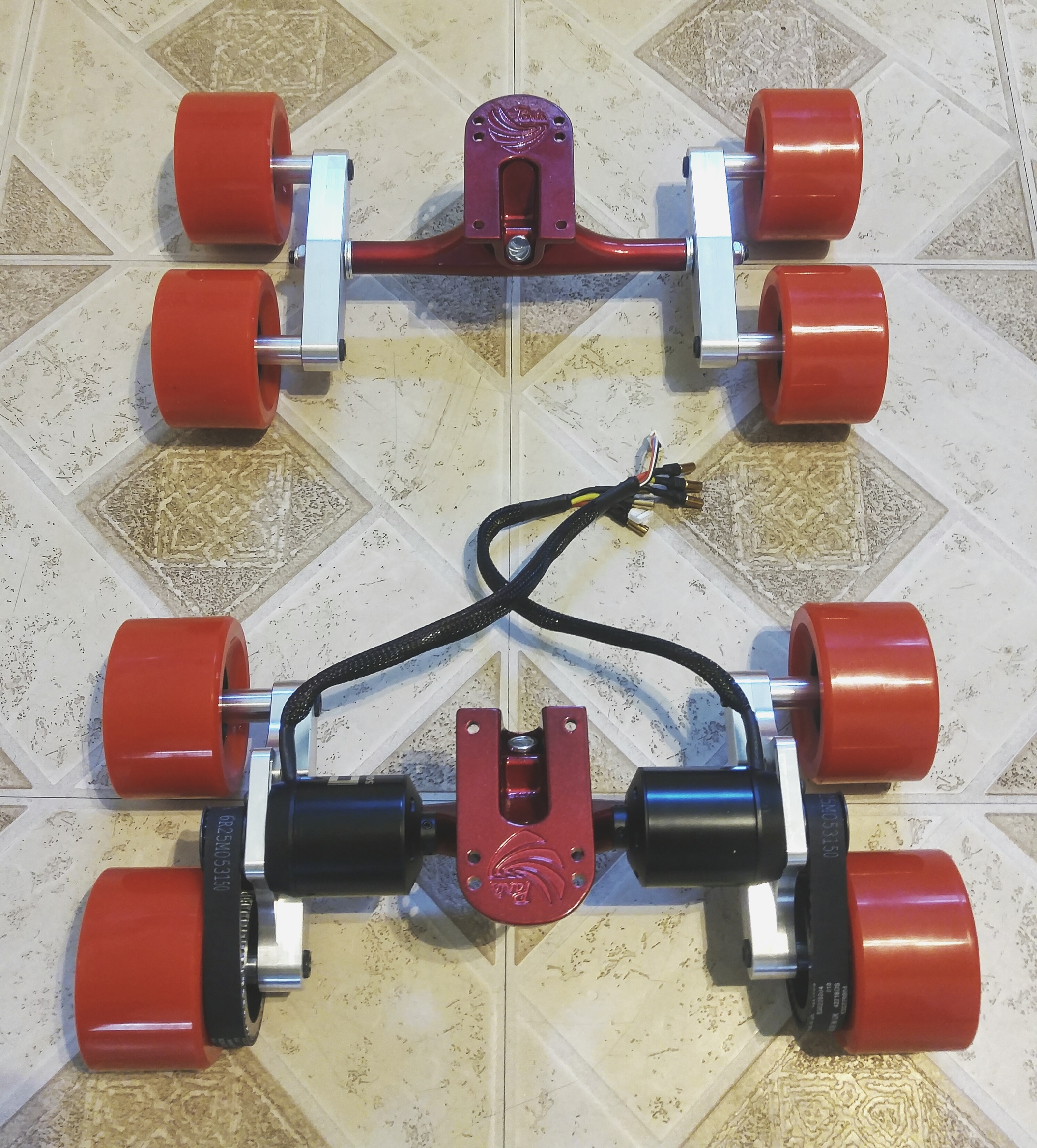
It was only after I pressed in the inserts that I realized the front mounts didn’t need to be nearly as offset as the rears, but we’ll see how it looks once I get some wheels on it.
I also finished another piece, the VESC enclosure. I based the design off of the other one I made. Still need to make the bridge for the top MOSFETs, but it is mostly ready to go.
This was made with a slight radius on the two shorter walls to match the radius of the deck I will be using. I did some 3D milling with a ball endmill to get the contour just right. Will post more photos soon, but all the parts are still in the shop, and I’ll be heading out for the 4th of July weekend.
I also got some work done routing some channels into the board to run the wiring. The front and rear channels are for headlights & taillights, while the middle one will run power from the battery enclosure to the VESC enclosure.
Here’s a quick picture of the battery enclosure I made out of some sheet metal and some CNC aluminum end caps. I secured the end caps to the sheet metal with some JB weld on the inside to keep things strong and sealed. The holes in the end will house some plastic aviation plugs that I will use for charging (middle for main power, and two sides for balance charge. The 10S4P battery is actually two 5S4P batteries that my loop key connects in series. When the loop key is disengaged, I will balance charge as two 5S packs. I ran this setup on my last board with zero issues).
Very cool. Nice looking mounts. For some reason I thought you were going to power each pair of wheels with one motor, but I guess it’s not really necessary. I keep looking at this setup and thinking the next variation would involve 4wd with some custom tank wheels and tank treads.
The design I have should be modifiable for a 4wd setup. It would require a tensioner pulley to keep the motor pulley having enough teeth of engagement. I’ll consider upgrading to 4wd if I have traction issues.
Love the design so far! Are you concerned about any wheel slip when accelerating or braking? Only asking because you’re limited to 1/4th of your weight on each of the powered wheels at best. I’m also loving the enclosure you’ve come up with. Guessing the battery enclosure is 5052? How thick?
I’ll actually be attending WPI next year, and am also working on a diy board. We’ll have to meet up sometime, I’d love to see this monstrosity in person.
We shall see how well the wheels grip the road. I’m planning on keeping the VESC settings pretty gentle. If I run into issues, I can modify the motor mounts for 4wd.
The enclosure for the VESCs is billet 6061 Al, and the battery enclosure is made of some sheet metal I found at home depot and some 6061 end caps I made and JB welded on.
Unfortunately, as I finished building the board, I ran into issues with my VESCs just that I am now resolving. One VESC was from my old build that I just had repaired by someone at Enertion. It blew its DRV upon motor detection (checked for shorts, none), and the other VESC I bought off of a friend doesn’t seem to want to send any current through the motor despite showing me no faults with the DRV. Might be a little while before it gets up and running due to the fact that I don’t have the money to shell out for 2 new VESCs while I figure out what is wrong with these.
Congratulations on your decision on attending WPI! What’s your major?
Wow, quite unfortunate that both VESC’s died on you. Good luck on getting that resolved. Did you even have the opportunity to see how it spins? Also, I think we’d all love to see some more pictures of the full setup if you had the chance to assemble or have any on hand.
Just resolved the issue. New FOCBOXs on the way to replace the broken 4.12 boards! Really excited to see how well the newer design works on my eSk8!
Never got to see the wheels spin, but during the motor detection of one of the VESCs, got to see the motor spin! It was very quiet, and seemed very well balanced. Looking forward to seeing it with the new FOCBOXs!
Not much else to see for now, but here’s a picture of the new deck with the trucks on it. I routed out some channels for some through-deck wire routing. Should be so much cleaner than my older builds with external battery to ESC wires!
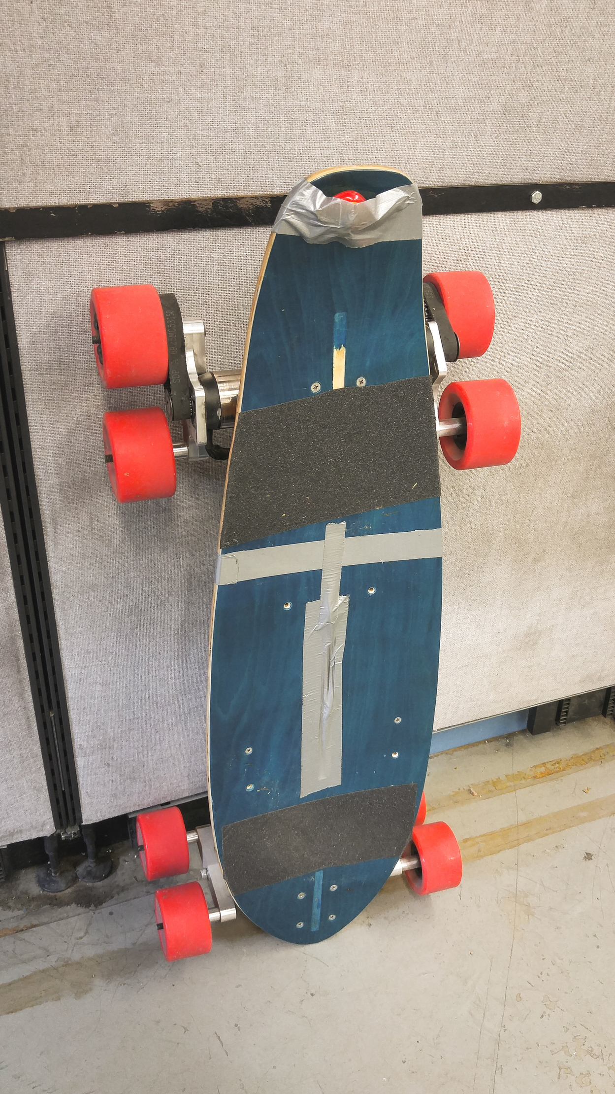
Well, I guess this is a little past due since I have been riding this around for a few days. I finally got too impatient to finish everything before assembling and testing the board. So, here is the board assembled!
I will admit that the Tupperware ESC enclosure is pretty hack, but it has actually been working really well as a substitute for the 4.12 enclosure I made (that doesn’t fit the FOCBOXs). I’ll be making a new one that has the features of the FOCBOX aluminum heatsink so I don’t have to use the one included with the ESC, which will allow me to make a lower profile enclosure.
I didn’t end up covering the entire deck with grip tape because I realized quickly after my first test run that I want to move to a different style deck, since I hadn’t expected the motors to run into the deck while turning. I’ll be moving to this style deck for more clearance. Any suggestions for brand? I’ve never spent more than $40 on a deck, and am ready for something a bit higher quality, in the $50-$100 range. I might make a new thread for this topic, who knows.
You may also notice the cans of the Ollinmotors have turned silver. I removed the black finish using scotchbrite. I did this because I let someone ride my board, and he accidentally messed up the finish on one of the motors. When he turned the board around by hand, one of the motor mounts flipped upside down. He foolishly rode the board 100ft down the road as I chased him yelling at him to stop! Amazingly, the only damage to the motor seems to be to the surface finish of the can.
Also, please excuse the hack tail light, was put on in a pinch to do some night riding!
I’ll upload some video footage of the board working once I get around to making some. Need a pole mount for my GoPro…
Well, I regret not posting here for a while, but I’ve been so busy lately with work! Thought I might just show you guys a teaser video of the board. I apologize for the portrait video, it’s the only one I have of it! It was a snapchat…
Unfortunately, I don’t have any other videos of the board… was too busy riding it to and from work! Now that school has started, I should have some more weekend time to actually work on the thing, especially since I need to repair the CANBUS chips on the FOCBOXs. ESC won’t boot without them.
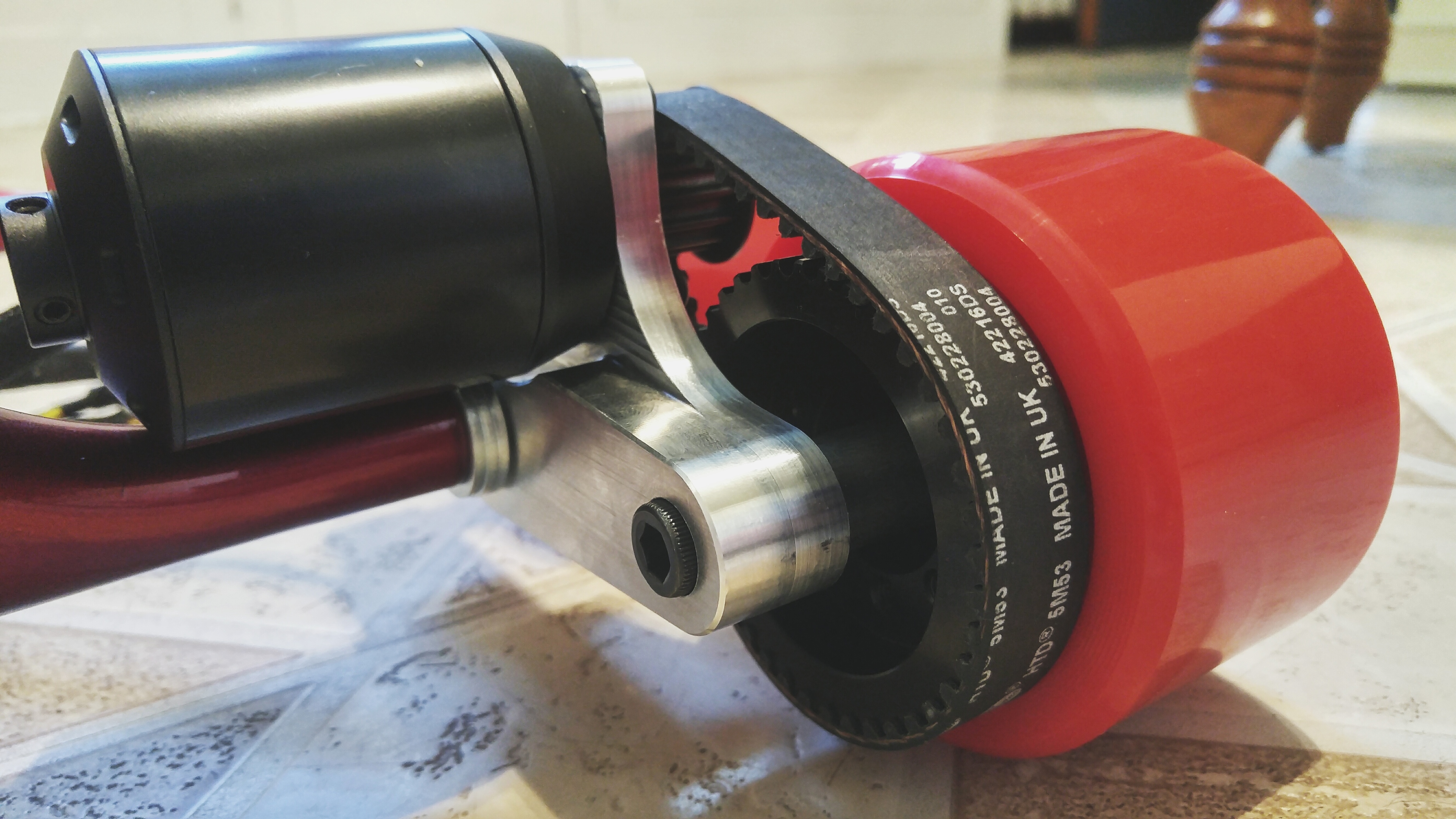
I also need to redesign the motor mounts, as they are wearing on the sleeve bearing, causing the motor to scrape the truck! Ooof… Time to use dual ball bearings. That should fix the problem.
I’ll be moving to a new deck as well, to avoid the motor rubbing the deck during turns. Here’s a picture of the deck.
I’m also designing a new FOCBOX case that will enable direct mounting of the boards to the enclosure, and replaces the original aluminum cases. Need to add some holes for the motor wires. Here’s a pic.
Hey guys, I feel like I owe you a final post on this thread. Unfortunately, I am bringing the 8 wheel project to an end.
Over the summer, I rode the 8 wheel, and things kept breaking on it, and it never felt like a finished product, hence why I never bothered to post pictures of it here. I’ll run through a few of the troubles I had with it.
First, the sleeve bearings I used on the motor mounts didn’t last long, as they wore unevenly due to the torque on them from the wheels being so far out. I moved to bearings, which solved this issue.
Before long, the motors became very scratched up, due to the motor mounts flipping upside down. It was always a pain to set the board on the ground, because they had to be oriented the right way or they would scratch. Oh well, I thought.
However, the motors condition soon worsened. They quickly began to rattle whenever I went on a road that wasn’t perfectly smooth. How uncool to be riding down the street on a rattle trap. No thanks!
As if that weren’t enough, the fact that the motor mounts pivot began to prematurely wear out the wiring on the motors! I was rudely awakened to this fact while going 20MPH. I hit a slight bump, one of the phase wires lost connection for a split second, and the FOCBOX freaked out and full braked the motor. I flew off the board and sustained some pretty good scrapes, but nothing serious. I’m glad I was wearing a helmet.
After this episode, I decided to discontinue the project. I didn’t see any way of keeping the motors from getting destroyed from vibration, and the board was way too heavy to be practical, I’d estimate around 30lb.
Do u have any final pics for thr build? There’s a new thread now about tandem trucks / wheels from china - taobao, not sure whenever someone would order but I think for experience it would still be interesting to ride it.
How was the riding compared to normal board? Does the extra wheels add significant rolling resistance? Did it absorb / overcome bumps better?
Quite curious why the motors didnt last long and got banged up, I.suppose there was some movement for the wires but otherwise they are on top of wheels right?
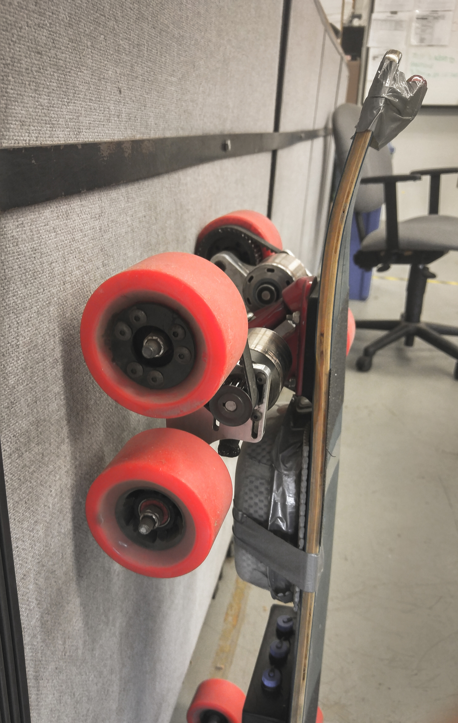
Well, one of the problems was because the motors were on top, they tended to want to turn the assembly upside down, since the center of mass was above the pivot point. Hence, the motors would oftentimes end up on the ground if you just set the board down normally. Even worse, if you accidentally hit the gas while nobody was on the board, they would immediately flip upside down scraping them up.
The important bit to realize about the flaw of this design is that the tandem truck uses pivot motion to absorb shock loads. So, if you drove over a reasonably moderate crack, there would be a large acceleration of the entire arm, along with the motor. This shook the motors to a very poor condition in no time. Now they rattle at the slightest hint of a rough road.
That being said, the board handled beautifully while the motors lasted. It literally more than halved the impact of large bumps on the road. I once drove through a pothole (with reasonably rounded edges) around 3 inches deep and 10 inches in diameter at 18MPH and I barely felt anything, a moderate dip, but nothing to throw me off balance. On the other hand, small bumps, cracks, and roughness of the road were not improved, if not worsened a little.
Steering was about the same, my turning radius was slightly wider than a 4 wheel, but not bad. High speed stability was no issue. The wide wheelbase also made the board feel very locked in and stable. The only downside performance wise was the fact that I was only driving two out of the eight wheels. This is the equivalent of having a single drive, but braking is made even worse, because the driven wheels are all the way back, where there is the least downforce while braking. This resulted in the wheels locking up a fair amount going down hills, though I’d say locking or sliding the wheels is better than skipping teeth on your belts.
Here are a few photos of the build, I thought I didn’t take any photos for some reason, but managed to find some.
Routing out the wire channels! I bought a dremel tool for this purpose. They make a routing adapter for it, so I made a template to fit the router guide, and made these slots, and drilled the holes.
IMO my favorite build in terms of looks. I only had 9" griptape at the time, so I did what I could with the resources I had. I used my school’s laser cutter to cut the design with all the holes and the arrow. Note that the motors have their paint removed, because they were getting so scratched up from being turned upside down all the time.
The underside is very clean due to the wire routing through the board. I must say, from this point forward, I am mounting as few wires outside the board as possible from now on. Not only does it look better, but it also forces you to think more about cable management, and in the end come up with a better design.
My car broke down this summer, here I am going to the auto parts store on my only working vehicle at the time! The board handled the extra load with ease. I was able to tow 50+lb of equipment, not to mention the extra drag of the underinflated tires, without the motors overheating! I did take a longer route home to avoid hills, but it still had to climb up a 15% slope and brake down a 20% slope.
If you’re curious what the board looks like now, head on over to this thread:
Thanks for the long description, anyways I think you still should add your crazy 8 wheel board to the http://esk8builds.com site, as it sure inspires to think out of the box in a way
Does not matter it is decommisioned now and parts already used for another build
As about the problem with “fliping” trucks/motors, did u think about installing some sort of end stop for the pivot to stop moving further? I can imagine it should have been of rubber or something to minimize the impact but non the less, if there was space for such feature maybe it would have helped
I thought about making some sort of mechanical pivot limiter. It probably would have solved some problems, but the vibration and weight issues would still remain.
Still glad I went out of my way to try something new! Someone’s gotta break some new ground in this field!