The pack only needs to be charged to 43.2v (3.6 x 12) not 43.8 (That is for 3.65 lifepo4 cells) Not sure if this is correct. Please advise me why if it isn’t correct.
The over discharge protection of this bms is too low for the A123 cells (2.1 ± 0.05 V) you will need to monitor this with the VESC low cut off voltage at start 2.6V and finish at 2.5V.
laboratory settings are not the same as real world use. A great number of people are using this cells for other applications and all the charge/discharge logging point to the sweet spot of 3.6V - 2.5V range to increase the life of the pack. The over charge will not be as detrimental compare to the over discharge but will affect too.
About the examples, all power tools using this batteries cut the discharge at/or around 2.5V.
That’s the laboratory setting cut off for marketing porpoises. It can be use but not recommend. If you look closely to the 2 top graphics on the pdf you’ll notice on the left side voltage axis. that the initial voltage drops in a exponential way (really really fast) wich means that there’s not that much usable capacity in that voltage range.
The bulk of the usable capacity is in the nominal voltage range. Going now to the right side of the first graph after the 2.5V on the 140W - 180W usage range the discharge curve drops exponentially again wich translate once more in little usable capacity after this voltage range.
The alarm in my pack, I just use as a volt meter just to check the voltage, this alarms just go as low as 2.7V so I don’t use the alarm , I have confirm that from 2.8 - 2.5 the pack still have 30% of the capacity.
This is the main issue with the lifepo4 cells that there’s no way to know the depth of discharge, because of the flat discharge curve and the exponential way in wich the capacity finishes.
But if you are going to use a VESC to manage the cut off voltage just use 31.2 V for the start voltage cut off and 30V for the end voltage cut off. That way your bms will handle the charging and VESC the discharging.
Thanks for your input!
I’m using dual TorqueBoards 12S 120A Car ESC so i might be able to set a correct voltage cutoff, but might not. I need to check the settings.
I eventually plan on investing in 2 VESC sometime down the road as I just spent a bunch of money on this pack and a Hi5ber Raptor that I ordered http://www.hi5ber.com/#!raptor/ca1y
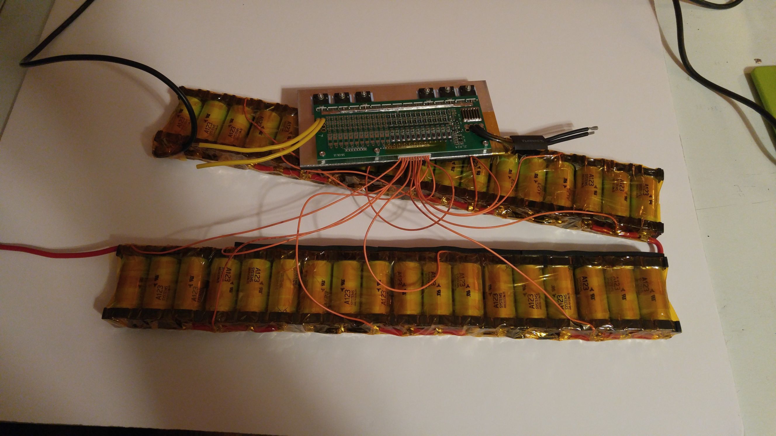
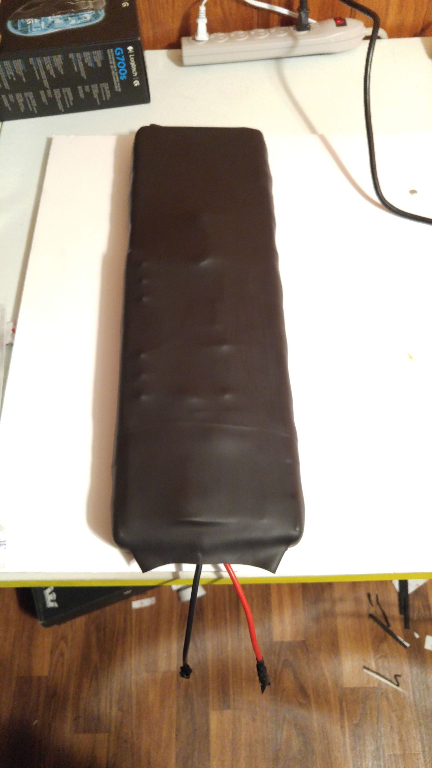
If anyone has questions about the tools I used or my process I would be happy to help. I still have to splice in my charger port etc… I will post a full board build thread soon.
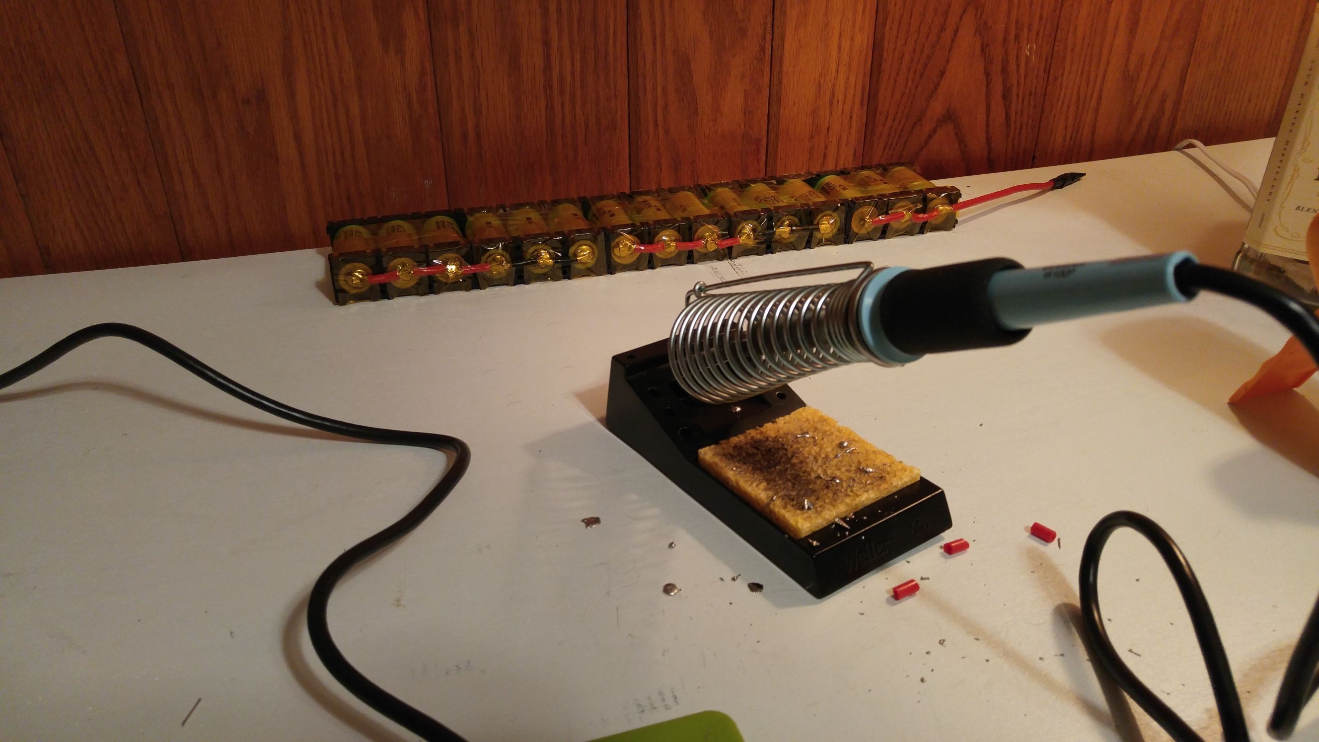
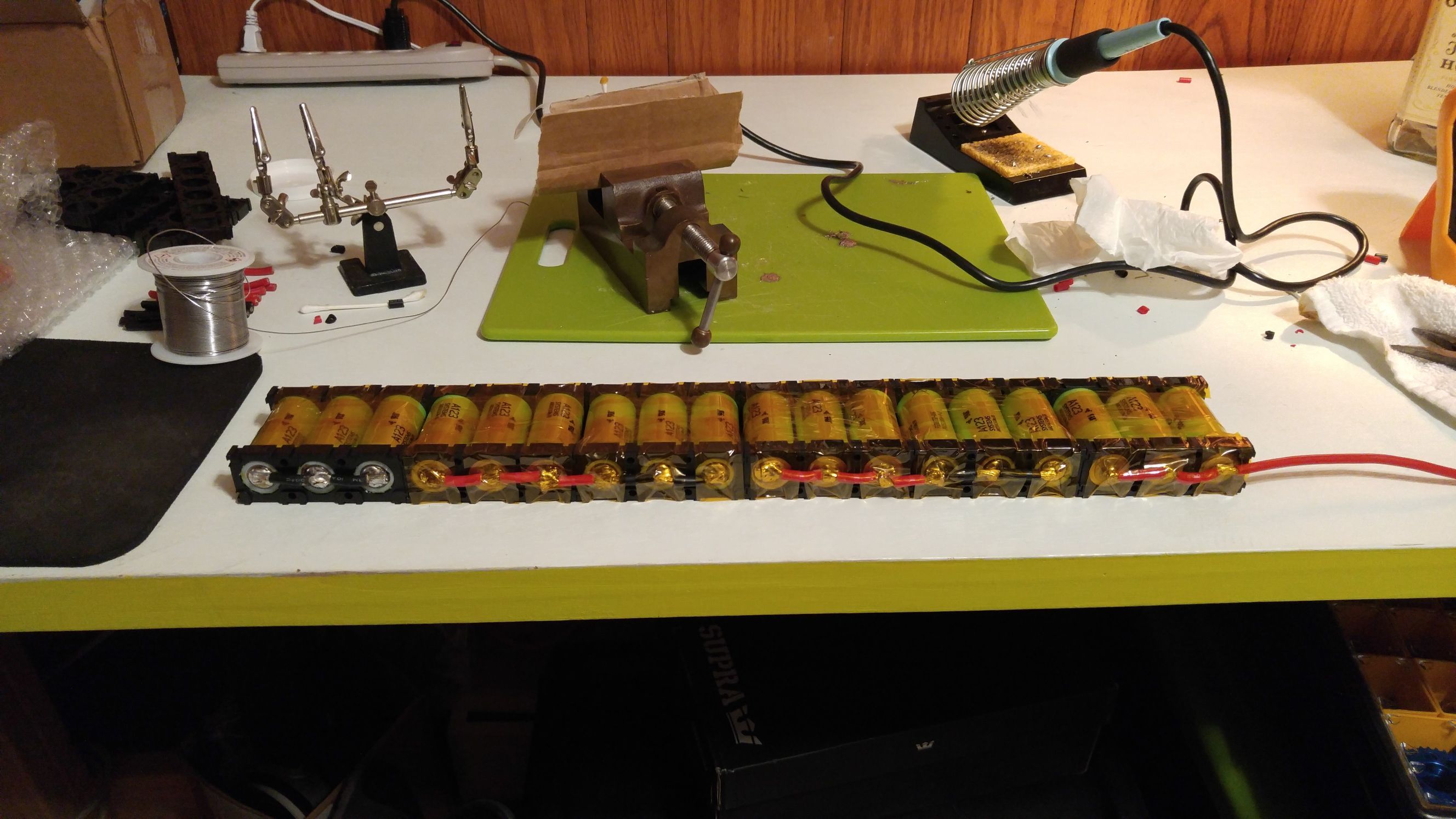
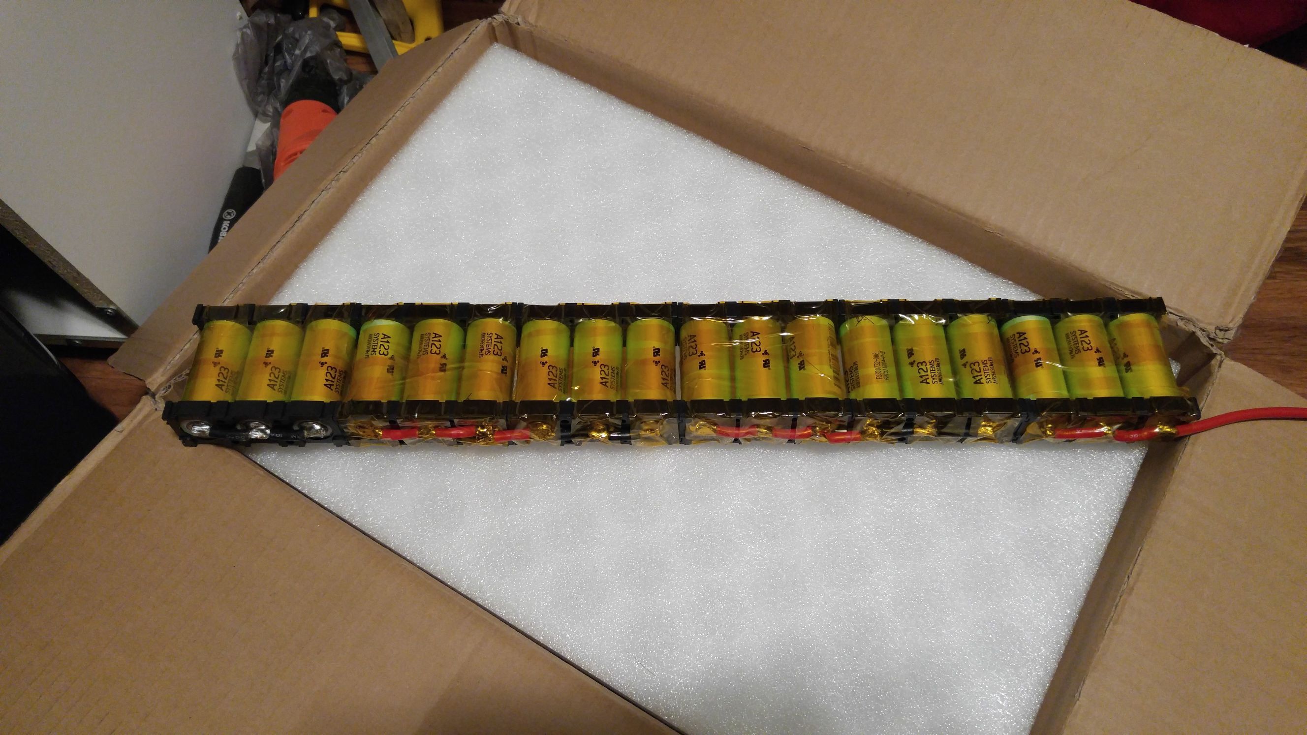
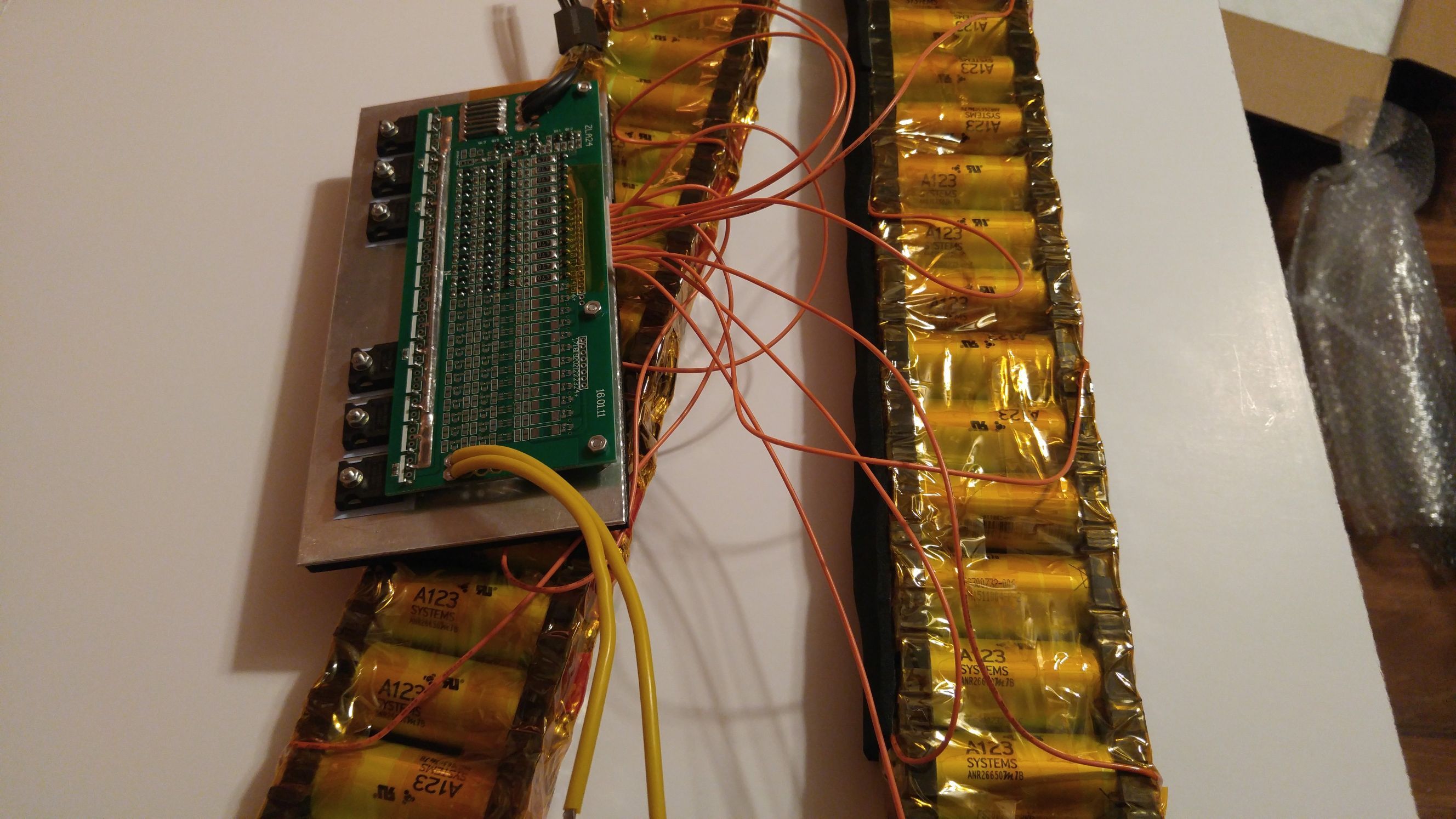
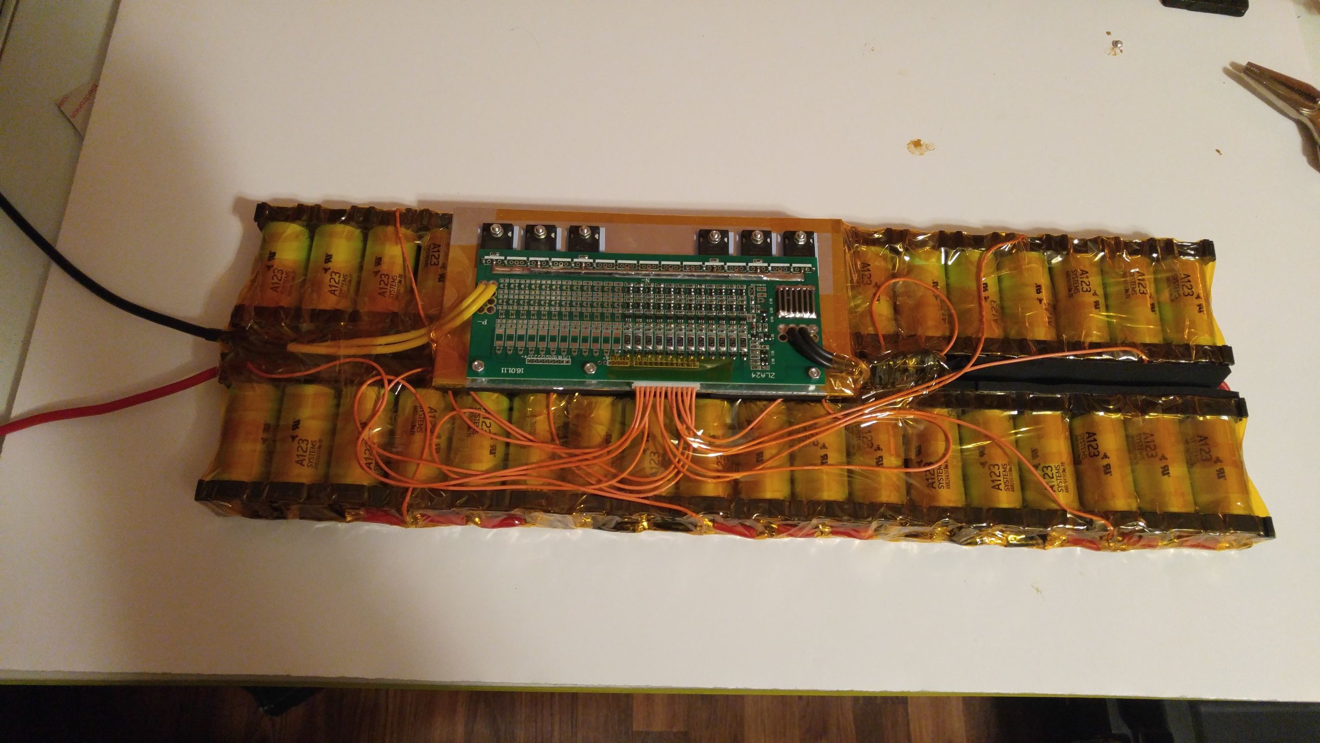
I decided the sleds I purchased would be too much of a pain to make them work,especially since I would have to remove the tabs to solder them and then snap them back into place in the plastic holder. Also reading about nickel strip sizing given amperage I decided It would be more reliable to directly solder the cells.
I used 10AWG silicone wire, some turnigy and some superworm.
Dang this battery probably costed a hell of a lot… But it will last super long. I think I will stick to regular Li-ion 18650 packs but this is pretty awesome.


 I’m using dual TorqueBoards 12S 120A Car ESC so i might be able to set a correct voltage cutoff, but might not. I need to check the settings.