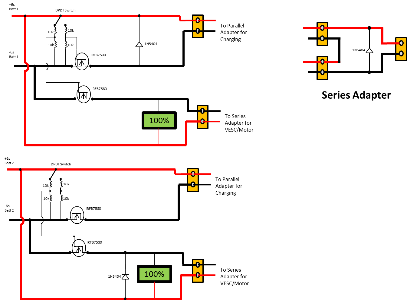
Hey, so I drew up this design for a power switch for my board running a 12S setup (2x 6s in series). If switch is in one position the packs go to a XT-60 Parallel adapter, but if flipped the other way they are in series and hooked up to the VESC/Battery monitors through a series adapter. I’d like a few second opinions on this design before I go out and implement it. Thanks 
seems really complicated, and really bad if something goes wrong… why not just get a 12s bms and charge/discharge all on 12s?
For a few reasons: 1.I’d like to avoid having to unplug the VESC for charging 2. I’ve Heard that Parallel Charging is preferable over series charging 3. Would like to have a On/Off switch instead of plugging/unplugging wires
It should follow the same basic idea used in @JdogAwesome 's power switch
Why do you have a diode between pos and neg?
the power switch alone would take care of 1 and 3, and for 2 thats mostly just because cheap rc lipo chargers mostly come in 6s max, so charging in parallel at 6s, is easier than finding a 8s+ charger… but a bms would take of that.
the thing is, you took something very simple, and solid. and make it it a recipe for shorting lipo/lion packs for rocket powered boards i guess? 

mostly i’m just saying there are easier more reliable ways of getting what you want
hmm, ok. Could someone please explain to me what a BMS is and how it works? Or point me to some good reading on them?
Been looking around a bit, so I already have this charger, https://www.hobbyking.com/hobbyking/store/uh_viewItem.asp?idProduct=58285 If I were to go the BMS route would this be sufficient http://www.ebay.com/itm/44V-48V-50-4V-12S-30A-Lithium-ion-Li-ion-LiPo-Li-Polymer-Battery-BMS-PCB-System-/221274094989?_trksid=p2352135.m2548.l4275
Are there any cheaper alternatives? or is this pretty much par for the course?
Hey @dstnceswmer thanks for tagging me. Your design for a series/parallel adapter is accurate and it would work, though like @saul said, it just kinda over-complicates things. First off you would need to have 2 separate switches on the outside of your board for parallel and series as well as a balance port, and a port for the main charging leads. This would mean that you would have more holes to make, more connections that could break, more areas for water to get into, and just generally more things to go wrong and on EBoards you want it to be as simplistic as possible, I learned this the hard way lol. Im not trying to bash on you or anything im just kinda pointing out some possible flaws with your system. Also where did you hear that parallel charging is better than series? Ive only ever heard that series is better than parallel charging because you need less amperage, but higher voltage, to charge in the same amount of time. I would recommend just using a 12S BMS and having a simple DC jack on the outside to charge the board, I seriously wish I had done that with my board. Having to plug my balancer into the board every time I need to charge it has been INSANELY annoying and has caused many many problems. Having a closed system would be preferable.
For a BMS you can find them on a ton of different websites, but you may want to contact @longhairedboy about BMS’s because he works with them a lot. Also have a look HERE for a ton of different options of BMS’s. If you want to use the built in over current protection, which is what the amperage rating is on the listings, you would need to have one of probably at least 30A or more. Though in one of @VladPomogaev videos he just bypassed the over current protection entirely by hooking his switch up directly to the batteries instead of using the two separate terminals on the BMS. Also a lot of times the traces on the BMS are far to small and will melt far before the over current protection kicks in lol. Link to Vlads video about BMS’s HERE
Thanks for the great feedback @JdogAwesome! I’m definitely convinced of going the BMS route and just using 1 mosfet and a switch for the Main’s power. I’ll upload a sketch in the morning. For now though I was thinking of ordering the
http://www.batterysupports.com/44v-48v-504v-12s-60a-12x-36v-lithium-ion-lipolymer-battery-bms-p-270.html
as it has the 60A max that the VESC will be set at and is rated for 12s since I am running 2x 6s in series. Does this look like it will get the job done? The only issue is long delivery times 
As for the question of parallel charging being better, I’m sorry I don’t remember where I read that, my guess is it was referring to an easier way to charge 2 6s packs vs two chargers or something.
That BMS looks awesome! A little pricey but it definitely looks of good quality and the max over charge is 4.2 instead of 4.35 or whatever some have lol. Also what kind of setup are you planning on running, single drive or dual? And im still selling my MOSFET switches if your interested 
FYI in your oignal schematic you have a diode also going across the series adapter leads, but you only need one near the MOSFET itself.
Thanks for the offer on the switches, I wil probably make my own though as all I’d need to buy is the fet (have most of the other supplies I can scavenge from work). Curious though what price are you selling them at?
I am using a single motor setup with https://www.hobbyking.com/hobbyking/store/uh_viewItem.asp?idProduct=36657 Already have it mounted to my truck via an aluminum mount welded. Also just ordered some nice large 97mm wheels to give plenty of ground clearance. I’ll prob start a build progress thread where I’ll post some pics.
Also I was looking a bit at setups that only uses the BMS for charge, since I can use the VESC for discharge protection. This would hopefully allow me to get a bit cheaper BMS.
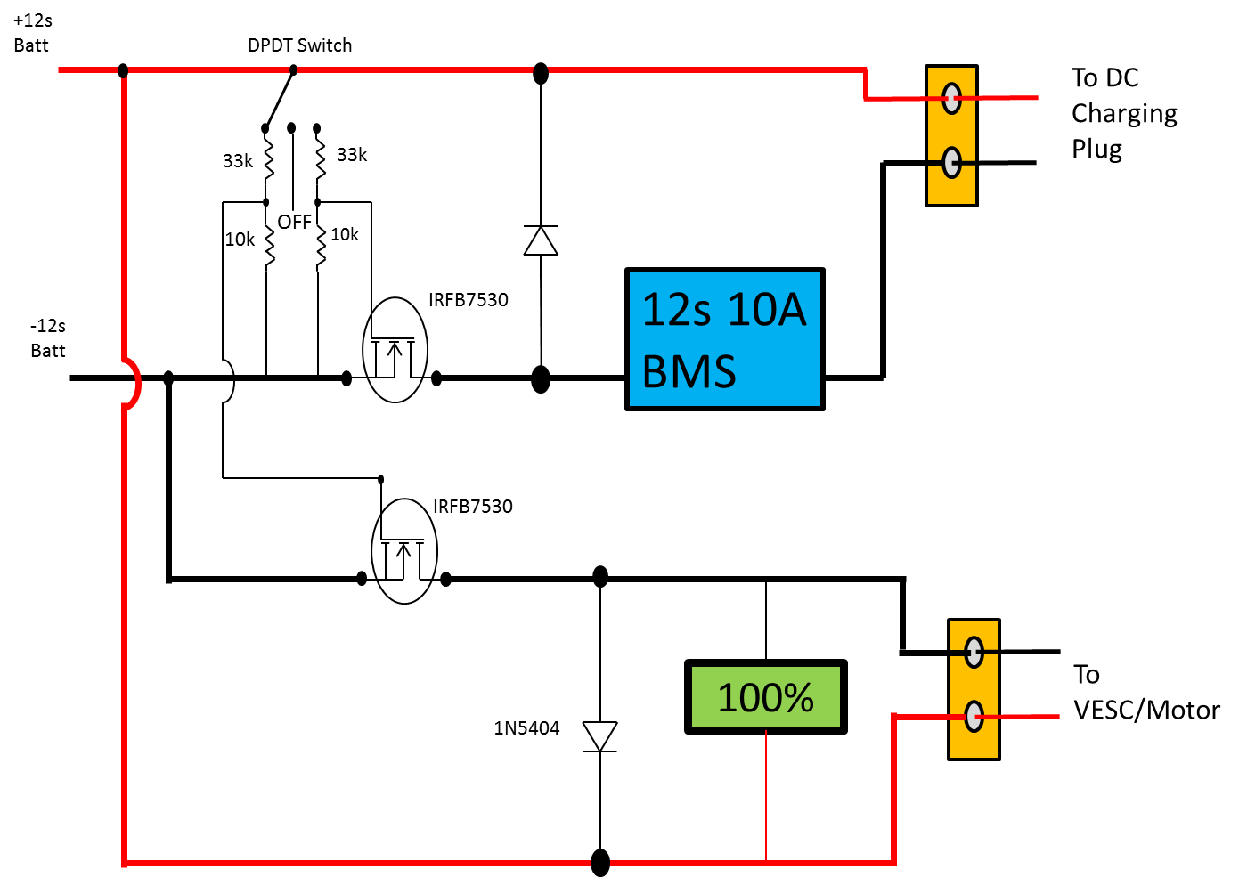
Anyways, here is the (hopefully) final schematic (doesn’t show the balance leads to the BMS) for a system with a high current (60A) BMS.

And her’s one for a lower current BMS used only for charging, with a second Mosfet to bypass the BMS during charging.
Glad you found some better options.
I have the same motor on 12s and 97mm flywheels. 14t/36t has really good torque. And still hits 24+mph.
Sweet! I’m looking forward to getting it up and running!
Take your time and double check, I rushed a bit oncw I had all the parts, then had to rebuild and fix all the tings I over looked.
Still had fun tho! Till I had to walk it home… Lol
Hey, I have been working on something very similar but took a different approach. I am planning to use a DPDT switch to alternate between 6S charging and 12S discharging. However, I’m a mechanical engineer… not an electrical engineer.
I tested the following configuration with AA batteries and a voltmeter to make sure it was hooked up correctly. I have not yet tried it with Lipos. I feel like I definitely need to add a flyback diode and perhaps some pull-down resistors? Can anyone give some insight or suggestions for my design?

Note: VESC -> Motor was simplified in this diagram as simply [M]. Balance leads are not shown
Intuitively that is what I was originally trying to accomplish. However I doubt you’ll find a DPDT switch that can handle the High current and voltage of the LiPOs. That is ewhy I tried having my DPDT switch controlling high power FET’s in my first drawing.
I found a DPDT switch rated to ~2.5 - 2.7 kW, but keep in mind there is an embedded safety factor in this number. At max load: 44V @ 60A equates to 2.9 kW. The switch is at least going to have a safety factor of 1.3, so really it should be able to handle 3.3+ kW
Can you explain your DPDT switch notation? I don’t fully understand your diagram. Thanks!