Glad you found some better options.
I have the same motor on 12s and 97mm flywheels. 14t/36t has really good torque. And still hits 24+mph.
Glad you found some better options.
I have the same motor on 12s and 97mm flywheels. 14t/36t has really good torque. And still hits 24+mph.
Sweet! I’m looking forward to getting it up and running!
Take your time and double check, I rushed a bit oncw I had all the parts, then had to rebuild and fix all the tings I over looked.
Still had fun tho! Till I had to walk it home… Lol
Hey, I have been working on something very similar but took a different approach. I am planning to use a DPDT switch to alternate between 6S charging and 12S discharging. However, I’m a mechanical engineer… not an electrical engineer.
I tested the following configuration with AA batteries and a voltmeter to make sure it was hooked up correctly. I have not yet tried it with Lipos. I feel like I definitely need to add a flyback diode and perhaps some pull-down resistors? Can anyone give some insight or suggestions for my design?
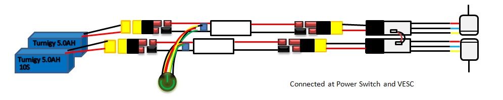
Note: VESC -> Motor was simplified in this diagram as simply [M]. Balance leads are not shown
Intuitively that is what I was originally trying to accomplish. However I doubt you’ll find a DPDT switch that can handle the High current and voltage of the LiPOs. That is ewhy I tried having my DPDT switch controlling high power FET’s in my first drawing.
I found a DPDT switch rated to ~2.5 - 2.7 kW, but keep in mind there is an embedded safety factor in this number. At max load: 44V @ 60A equates to 2.9 kW. The switch is at least going to have a safety factor of 1.3, so really it should be able to handle 3.3+ kW
Can you explain your DPDT switch notation? I don’t fully understand your diagram. Thanks!
Not much of an official notation on my switch, it’s essentially the same as you have drawn, Your pins 2/5 correspond to my poles that I have located on the + connection of each 6s battery. It then toggles between which FET it wants to turn on. Are you familiar with the concept of how a FET works?
Also do you have a link to that switch you were considering?
@dstnceswmer I was looking at the shcematic you made with the 60A BMS and that one looked pretty good, except for the battery positive lead. Though the one below it is again, over complicating things and could cause some problems. First of all a lot BMS’s need an input charge to “turn them on” beofore they will start doing anything, so when you bypass the BMS for charging you effectively disconnect the BMS and that would make it shut down. Also a very small amount of current leaks through the MOSFET, enogh to power maybe an LED but thats it, though this small leakage ive had measure at different voltages sometimes upto 3V which could cause some undesired affects on the BMS side. It could make the BMS thing that the LiPos are SEVERELY over discharged and it could freak the F out or god knows what lol. Now this is unlikely, obviously, though it could cause problems and as I said over complicates, and creates more possibility for problems. What would be best is to do what @VladPomogaev did and use a low amperage cheap BMS and just hook the battery straight upto the main switch for the board, bypassing the OC protection on the BMS. Below is an example of what I mean:
Also heres the pricing for my switches:
P.S. Why are you using 33K Ohm resistors? Just curious if you had a reason, they’ll work fine, you can use anything from pretty much ~1K-100K lol.
Hey @jmasta I kinda understand what you mean in your schematic you drew though the actual image is very confusing sorry. If you could possibly try to highlight certain parts of the schematic and try to make them more obvious and labeled better then I may get a better understanding of what your trying to do. Im not trying to be to harsh or anything just its a little confusing, though you have amazing hand writing lol, if I did something like that it would look like some 5 year old drew it. Also the DPDT switch you said you found that is rated at 2.5-2.7kW but could probably handle around 3.3kW would work kind of, I wouldn’t recommend using it at all. First of all im sure the thing is fricken beafy and would be an eye sore as well as a hassle for fitting in your board. Also when you first start up your board you have to charge the ESC caps and that draws a TON of instantaneous current, which causes that dreaded spark everyone talks about, and your switch might not be able to hand that and could fuse together. Also ever time you start the board the contacts would become oxidized more and more from the spark and would eventually need to be cleaned, which may be very hard in a closed switch. In conclusion I would HIGHLY recommend using either a loop key or a MOSFET switch in order to turn your board on and off. I originally used a PIECE OF CRAP fuse as a switch and it worked at first but over time It just created SOO many problems for me and I wish I had never used it.
that must be a monster switch, doubt it was made to survive the vibration of an esk8.
So I am going with the 60A BMS, already ordered it. From what I have seen the positive lead from the battery does not get hooked up to the BMS at all, only the negative lead and the balance wires. Below are a couple examples of wiring guides I am referring to. In My 60A BMS schematic I don’t see how the FET would leak any current when the switch is off, as the positive battery lead is physically disconnected from the gate of the FET? And the reason I have a 33k res in my switch circuit is to divide the 12s voltage down to around 11V to be appropriate for the Vth of the FET’s gate.


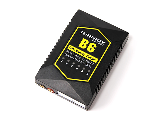
I was thinking of having a splitter on the discharge leads, one goes to the VESC and the other to a B6 charger, im guessing the balance charger will act like a bms (minus the discharge protections), that way i can leave everything connected inside the enclosure and just 1 plug to charge. Will add a drawing in a few min
So you’re just putting the entire charger inside the board’s casing? seems kinda like a bulky/heavy solution to 1 port charging. Why not just use a BMS and then a standard bulk charger for charging?
Not the brick, just the lightweight B6
I got this one… Works well…slow ito charge but it’s stupid proof…no buttons…seem to charge battery to 25v only but that’s perfect for long life
I wonder if it will be safe to have it connected all the time to the battery and if it will drain some charge over time.
I was actually wondering the same thing.
I have an additional question in relation to wiring the power switch at higher voltages as i am looking to do a 12 S or higher on a dual motor setup. I know its totally unnecessary but i was wanting to see if it could be done. Could 2 power swtiches be wired together in either of the following ways:
1: Have two entirely separate systems(independent batteries, power switches, vescs, and motors) and connect them at the power on buttion by combining the two ribbon cables into one button. And Pair the Vescs the normal way.( My thought is that becuase the power to the systems is seperate and the only way that the systems are combined is by the VESCs talking to eachother and the on/off being combined thus preventing overpowering anything and still allowing for a single remote.
I hope that i was descriptive enough for the idea to make sense.
Thanks for the help!