10S5P Battery Pack build log. 50 pieces of Samsung 35E cells

Turns out you can’t remove polls, so this poll will stay here.

  • Yes, I’m interested in a battery build log
  • No, I’m not interested in how you build your battery packs

0 voters


Part 1, Planning and prep work

You have decided to build your own battery pack and your new, precious and expensive cells have arrived from the supplier. If you didn’t already figure out what kind of battery setup you’re building, this is the time to do it, before starting to solder or weld anything together. There is also prep work that needs to be done to ensure safe and long lasting pack build.

How will the pack be fixed in place? In my case I’m going to use my current board’s execution style where the pack is friction locked in it’s place inside the milled space with the help of some vibration absorbing foam tape. So when the bottom piece is bolted on, the milled inside space is high enough to allow the cells to actually move freely, but when the foam tape is added it squeezes the cells gently in place.

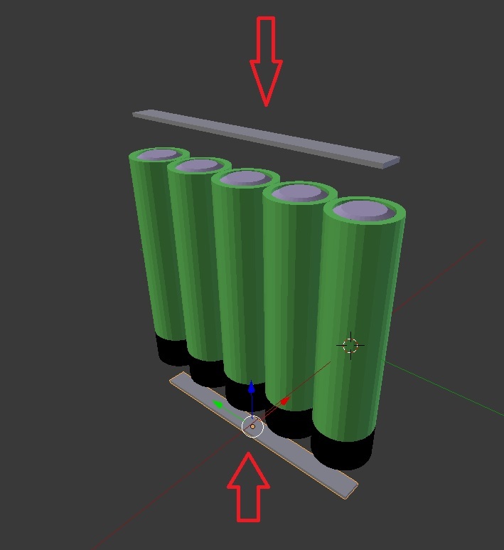
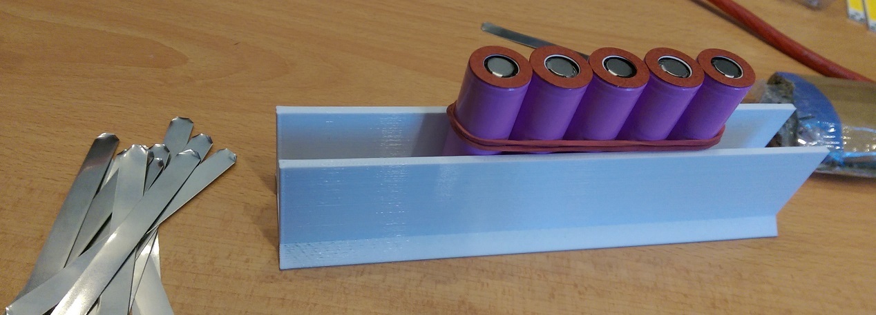
I’m going to change the layout of the cells a little bit from the earlier pack, which was shown above. I’m rotating the cells 90 degrees and stack them this way instead. The below picture is from a prototype deck, which wouldn’t have been able to fit the 10S5P configuration I now plan on doing.

So I redesigned the deck so it would be able to fit a 10S5P and sent the new CAD-files for milling

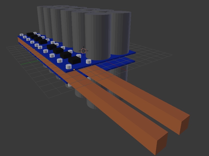
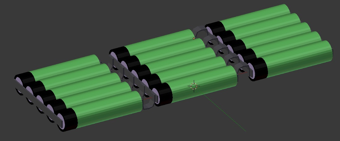
And here’s the overall connection layout minus the balancing leads.

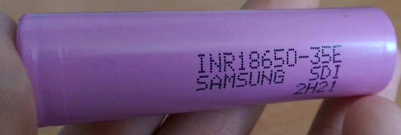
The cells are 50 pieces of Samsung’s INR18650-35E, 3450 mAh, 10 A. Bought from Nkon for 3.11€ ea VAT free with company VAT number. Shipping was about 16€.


How will you assemble the battery pack? I re-thinked the assembly process after my first battery pack and came up with a quite neat and simple plan to build it.

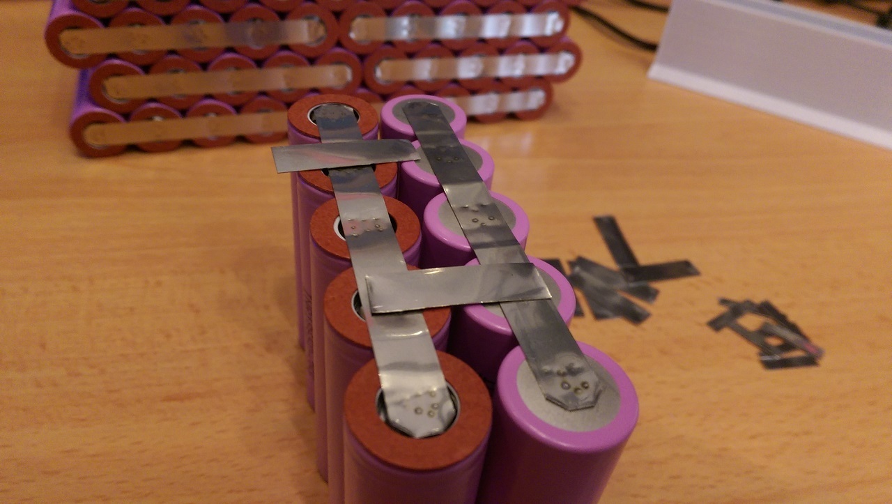
1st, I weld up 10 pieces of 5 parallel packs.

Then I connect the parallel packs in series with a couple short parallel tabs for better current carrying. I also will most likely add the balancing leads at this point.

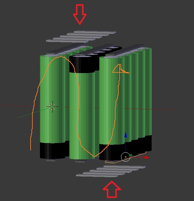
Then I will just fold out the pack into it’s flat form, which will then fit into the board.

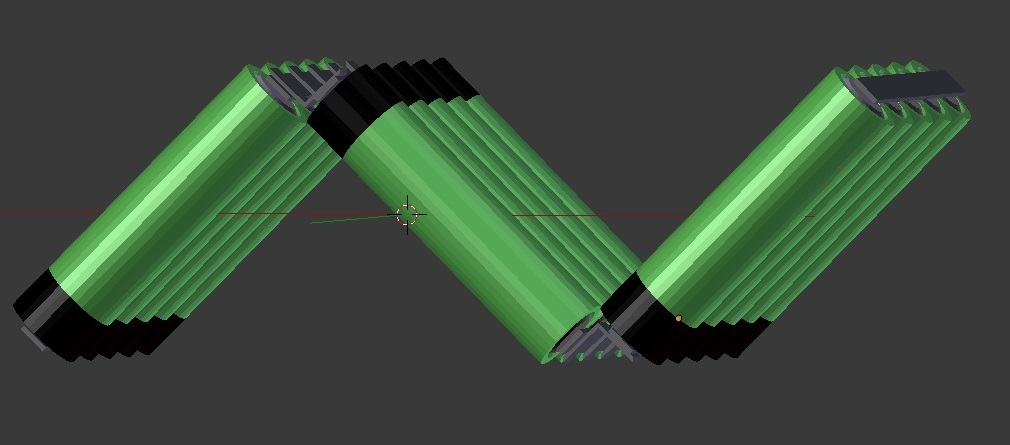
The bends in the image are over emphasized for better illustration purpose. Once I have the pack folded out I will add some kapton tape to secure it mechanically better together.


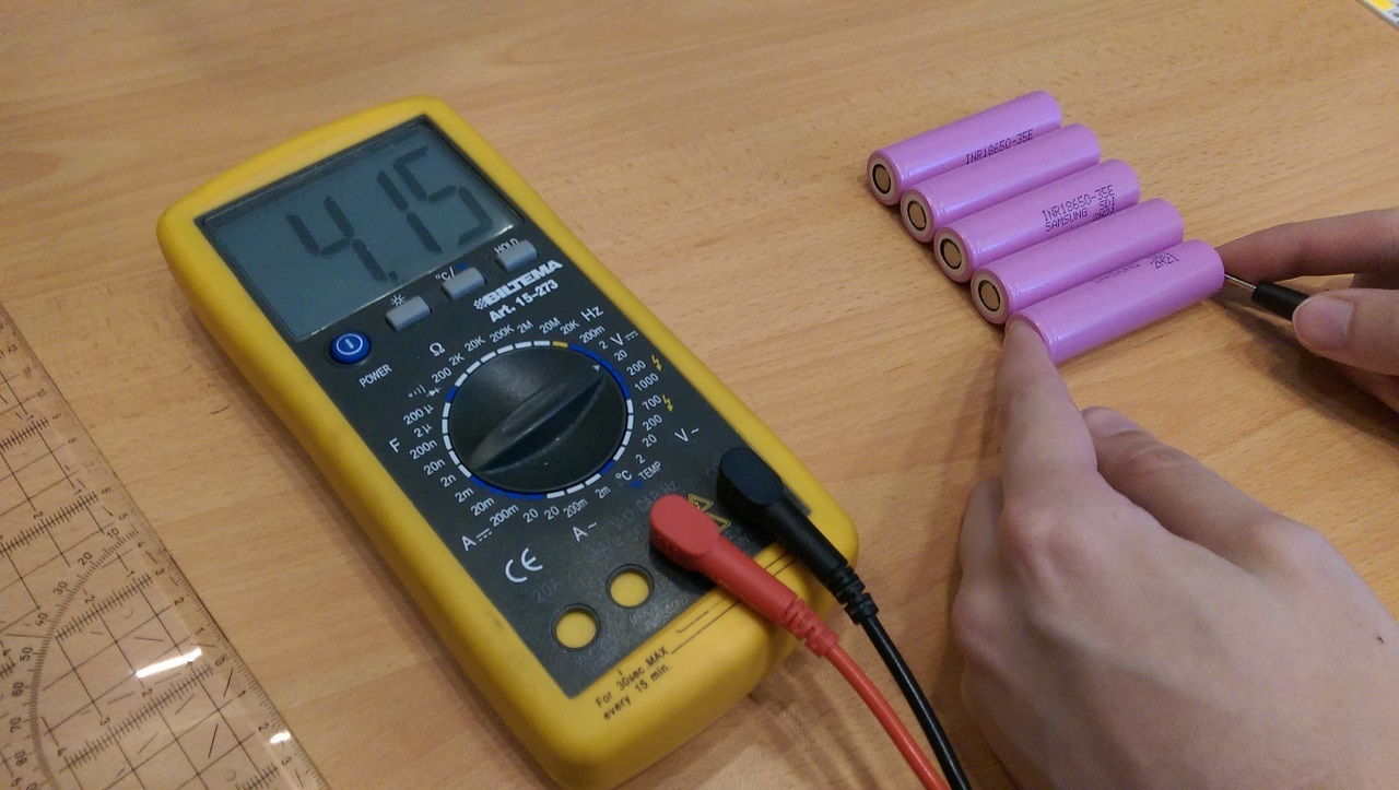
Now that’s the planning done, now the prep Before welding the parallel packs, care must be taken to ensure that all the cells that are to be connected in parallel have roughly the same voltage each. Otherwise you might connect for example, couple cells at 4.00 V with a one that is 3.50 V and that will cause a high current from the 4.00 V cells to flow into the 3.50 V one to even out the voltages and that might cook the cells due to the current. Worst case is that you have a fire.

In this case all the cells were around 4.13±0.02 V. I then did a final topping charge to the cells and got them all 4.19±0.01 V

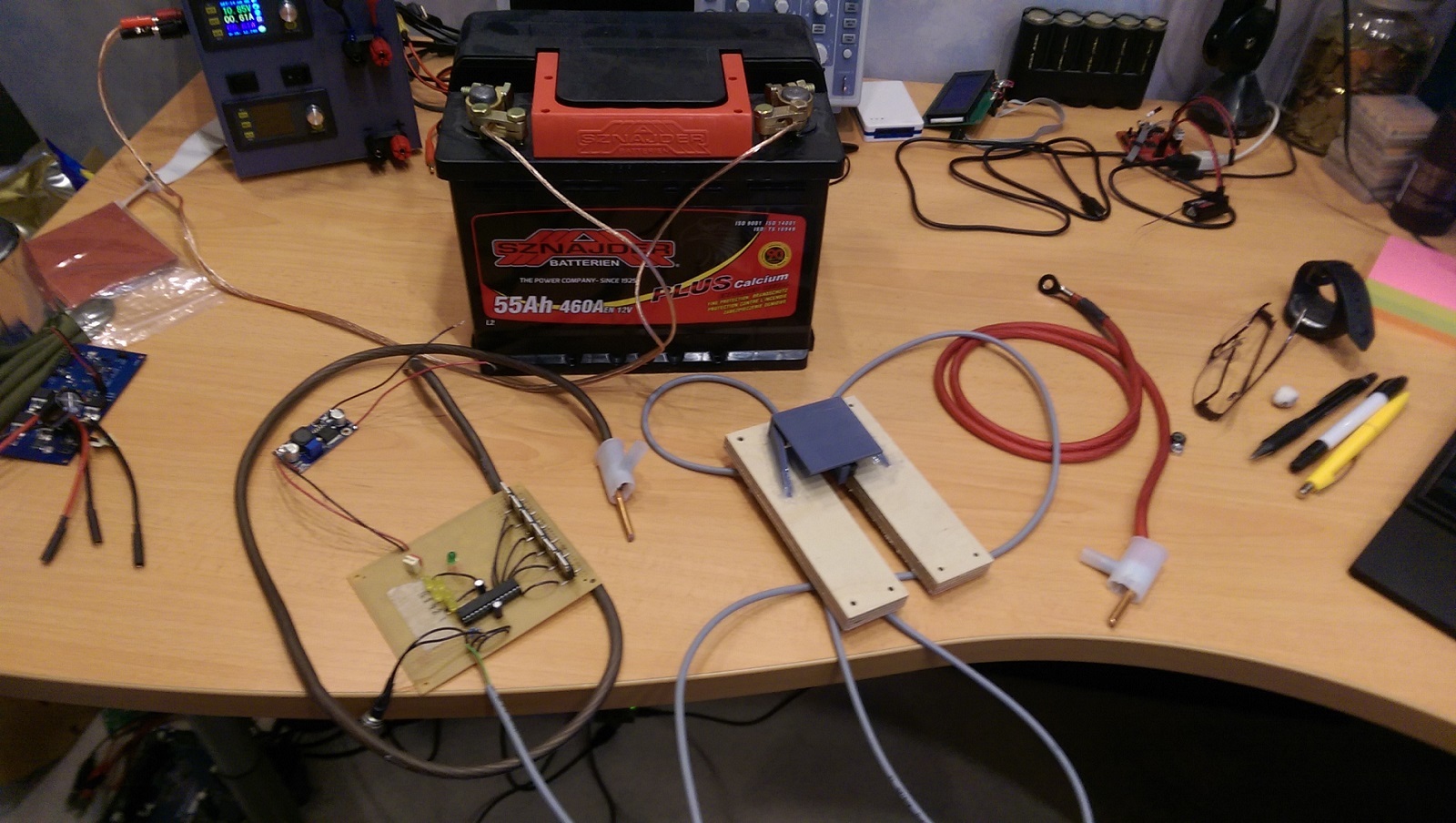
If they do differ then they should be charged with a charger to full voltage to even them out. Like I did earlier, before measuring the cell voltages. This setup is my solar panel charger, which is charging the car battery, which to the Li-Ion charger is connected to. Green energy folks right there.

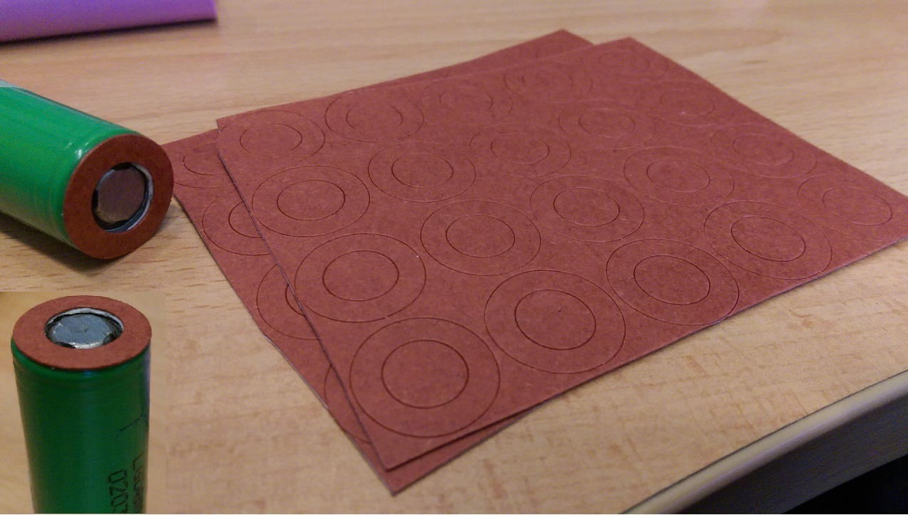
I also now like to add an extra protection to the positive end of the cell to protect from short circuits caused by excess tab temperatures, which could possibly melt the plasticy protective ring around the positive terminal and short it into the negative terminal shell.

DANGER CLOSE! The positive tab is surrounded by the negative terminal shell and should be protected from accidental short circuits! (Image from batterybro.com)

These adhesive cardboard ring add a little bit of thickness, but are much more resistant against mechanical and thermal stress. If you’re planning on soldering your pack together, I strongly recommend these, as the longer heat exposure will start melting the plastic ones. These were bought on ebay.

So to review the planning and prepping:

  • Figure out your pack configuration: 10S5P, 8S3P, 12S4P etc.

  • Figure out how you’re going to attach the pack onto your board

  • Think through how you’re going to assemble the pack. Tab connections, balancing leads

  • Charge your cells to same voltage before starting to weld or solder

  • Add extra protection to the positive terminal to protect from accidental short circuit to the negative outer shell, if necessary


Part 2, Welding and assembly (Unfinished and on hold, check post #6 for info)

We have our action plan together and our prep has our cells at the same voltage and the positive terminals are protected. It’s time to start welding! well… almost.

First we need to start testing and dialing in our welding settings. I usually start with the shortest pulse length and do a test weld and try to pull the nickel tab off of the battery and if it comes off easily, I up the power.

Turns out this legitimate pure nickel strip at this thickness (0.2 mm) is pretty dang good conductor, because I had to test all the way to max pulse length the welder could put out and only there were the tabs starting to stick well.

After testing out the correct pulse settings for the weld, I measure out the needed tab length for the parallel packs and cut them with plain household scissors, because the nickel tab is pretty soft, but I wouldn’t recommend using maybe the best scissors in the house still… I also snipped off the sharp corners for a little bit cleaner look.

I have 3D-printed a holder for the cells while I’m welding them that holds them in a straight line and I then add a rubber band to pull them together to make straight and tight packs.

First parallel pack done!

Halfway done.

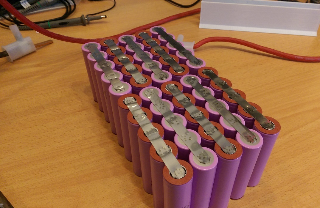
All 10 parallel packs done!

23 Likes

Tell something about your spotwelder too! I think seeing first hand spot welding experience is a rewarding thing! So just go on…

I think we got only a few documented cases about spotwelders on this forum… :smiley:

1 Like

I’ll start the build tomorrow, based on these encouraging results:


My battery welder uses a car battery with a DIY double pulse electronic switch with a foot switch.

The idea is based on this welder that I saw in a hackaday article. I needed to start welding my first pack together quickly so I didn’t bother ordering the custom pcb and parts, but rather compensated with a perfboard and components right off my shelf.

The controller gives an adjustable double pulse with the longer pulse being between 1-20 milliseconds and the first short pulse being only a tenth of that. I admit that it is not very aesthetically pleasing, but it was made with a pragmatic purpose to get building the battery pack.

I’m planning on designing a proper capacitive discharge welder with proper designed PCBs and an enclosure and a way to set the pulse length. I’ve been eyeing up the idea based on this design, but I’m most likely going to do some things differently. I just don’t think the car battery based solution is very good for a long term use, as I feel like the battery slowly degrades over use. http://www.zeva.com.au/Projects/SpotWelderV2/

4 Likes

well… as long as it performs as it should, no problem :wink:

Yeh I saw some earlier prototypes too of some of these arduino driven welders… the circuitry is a bit crazy if you got to do everything with wires and want to make it compact :smiley:

First part of the build log posted.

1 Like

Update on the build. I can’t finish it with my current welder because it doesn’t have enough power to weld the tab-on-tab connections which are needed for connecting the parallel packs in series. This is because the new legitimately pure and quite thick nickel tabs conduct electricity so well, that they don’t heat up to their melting point with the car battery welder. Against the battery terminals themselves it worked, but I had to crank pulse length to the max to make a decent weld.

I’m going to have to build a capacitive discharge welder to finish this build and that will take some time and this build will stay on hiatus meanwhile. If you have questions or anything related to this topic we can of course discuss about them here.

If you’re wondering about capacitive or dual pulse welding here’s a couple links on the subject: http://www.spotweldingconsultants.com/capacitive-discharge-welders/dual-pulse.htm http://www.powerstream.com/spot-welder.htm

And I’m going to build something based on this project: http://www.zeva.com.au/Projects/SpotWelderV2/

3 Likes

what thickness do the nickel strips have? I did not have any problems to weld nickel on nickel with my 0.15 strips from nkon and the arduino car battery welder (at a pulselength of ~14ms if I remember correctly). The endless-sphere topic on it even had people weld copper with it!

It’s 0.2 mm thickness and the problem comes when I’m trying to weld the tabs onto other tabs.

So I have a pancake of: Electrodes Series tab Parallel tab Battery terminal

It just can’t heat up the contact points enough to weld the tabs onto one another.

are you welding this pancake at once or layer by layer? I did mine layer by layer up to 3 on my series connections to allow for higher currents. I also added points with solder on the top most strip before welding it to the battery to be able to put some additional copper wire on top without heating the battery up too much.

I just updated the build log on the first post how it has progressed, but at the last image you can see the current situation. So when I’m adding the tabs to connect the parallel packs in series I can’t get them to stick, they just don’t weld well enough and come off too easily.

Actually here’s a picture of the problem weld.

So when adding the short series connection tabs, they are the problem at the moment.

@Maxid btw, can you post a picture of your electrodes you’re using on your welder? Just interested in the tip shape.

1 Like

Sorry I don’t have it around currently. I just used 16mm solid copper wire from home depot and filed it to be pointy

Something like this?

1 Like

yeah - however I filed it on all sides to have a round shape with a pointy tip - like a pencil. From what i heard the pointier the better as the current heats that point up even more than a “large” surface.

1 Like

Ok, I filed the pointy bit to be on the edge, so I can get them closer together when welding.

I see you´re using a 55Ah battery. That was my problem too. Got a new bigass 700A battery, tried again and now i´m able to weld at least 5 layers of 0,15mm nickelstrips with only 14ms timer :slight_smile: The other difference is the spotwelder itself. You´re using a different one. @Maxid and I are using the arduino Spotwelder:

2 Likes

My welder electronically is an equivalent to the arduino one, although not as cleanly executed. I might still go with the capacitive discharge welder, because then I don’t need to lug around a big battery to weld, but I can use a small and lighter power supply to charge the capacitors back after a welding pulse. It has also the added benefit of being able to give higher current pulses.

alright! keep us updated :slight_smile:

I guess I’ll update the progress on the new welder here. Anywhoo, the capacitor and MOSFET board design is pretty much done and I also did small 3D-model of the system in blender to figure out any immediate problems with it, but so far it seems pretty good. I sourced ebay for copper bus bar and decided to go with 10x10 mm size bar that I’m going to drill through some holes and then fasten them with screws onto the cap boards for minimum impedance.

PCB layout looks as such.

I plan on putting 4 of these PCB-modules on the first version of the welder. 24 pcs of 47000µF 16V El.caps https://www.digikey.fi/products/en?keywords=565-2620-ND 16 pcs of IRLS3034-7 MOSFETs https://www.digikey.fi/products/en?keywords=IRLS3034TRL7PPCT-ND

3 Likes

Caps for 100€ - wow. Wouldn’t an audio cap have been cheaper? @whitepony uses one and seems to get pretty good results. Looking forward to your results.

I’ll wait for @whitepony to give a reply and tell about his experience with his welder and if he has had any power problems with it. He can also tell his thoughts on this welder build of mine.

I checked out a couple of car audio capacitors’ ESR ratings, which were around 1.5 mOhm and with 24 of these caps in parallel they would have around 0.6 mOhm, enabling for higher current spikes, plus I think this design has a very good low impedance connections to it.

If he hasn’t had any problems with it, I can just replace the car battery with the car audio cap and it should then be able to provide plenty of amperage.